

Project 5.01 Cycling Colors with a Button
In this project, you'll learn how to cycle through different colors on the NeoPixels using a button!
The goal of this project is to change the color of the Neopixels every time SW1 is pressed. The colors will cycle between red, green and blue.
Project Code:
/////////////////////////////////////////////////
// 5.01 Cycling Colors With a Button

#include <Adafruit_NeoPixel.h>

byte dataPin = 10;
byte numberOfPixels = 2;
byte brightness = 10;
byte LEDSetting = 0;

byte SW1 = 1;
byte buttonState = 0;
bool pressed = 0;

Adafruit_NeoPixel pixels(numberOfPixels, dataPin, NEO_GRB + NEO_KHZ800);
void setup() {
  pinMode(SW1, INPUT);

  pixels.begin();
  pixels.setBrightness(brightness);
  pixels.show();
}

void loop() {
  buttonState = digitalRead(SW1);

  if (buttonState == pressed) {
    LEDSetting++;

    if (LEDSetting > 2) {
      LEDSetting = 0;
    }

    if (LEDSetting == 0) {
      pixels.setPixelColor(0, pixels.Color(255, 0, 0));
      pixels.setPixelColor(1, pixels.Color(255, 0, 0));
    }
    else if (LEDSetting == 1) {
      pixels.setPixelColor(0, pixels.Color(0, 255, 0));
      pixels.setPixelColor(1, pixels.Color(0, 255, 0));

    }
    else {
      pixels.setPixelColor(0, pixels.Color(0, 0, 255));
      pixels.setPixelColor(1, pixels.Color(0, 0, 255));

    }
    pixels.show();

    delay(250);
  }
}
///////////////////////////////////////////////////
*If you’re copying and pasting the code, or typing from scratch, delete everything out of a new Arduino sketch and paste / type in the above text.
In the loop() function, the first thing we do is check to see if a SW1 is being pressed.
buttonState = digitalRead(SW1);

if (buttonState == pressed) {
In this example a variable called LEDSetting is used to keep track of which color should be displayed. Every time the button is pressed, this variable is incremented by 1.
LEDSetting++;
After incrementing that variable, it needs to be checked to see if it is out of the settings range (0 - 2). If it is, it is reset to 0.
if (LEDSetting > 2) {
  LEDSetting = 0;
}
Next, the appropriate colors are loaded into the Neopixels based on the LEDSetting variable according to the table below:
| LEDSetting Value | Neopixel Color |
|---|---|
| 0 | Red |
| 1 | Green |
| 2 | Blue |
if (LEDSetting == 0) {
  pixels.setPixelColor(0, pixels.Color(255, 0, 0));
  pixels.setPixelColor(1, pixels.Color(255, 0, 0));
}
else if (LEDSetting == 1) {
  pixels.setPixelColor(0, pixels.Color(0, 255, 0));
  pixels.setPixelColor(1, pixels.Color(0, 255, 0));
}
else {
  pixels.setPixelColor(0, pixels.Color(0, 0, 255));
  pixels.setPixelColor(1, pixels.Color(0, 0, 255));
}
To display the new color we have to update the Neopixels using the show() function.
pixels.show();
Lastly, a crude debounce is used to prevent more than one press being read at a time.
    delay(250);
  }
}
///////////////////////////////////////////////////
Project 5.00 Using the Neopixels
In this project, you'll learn how to control the onboard NeoPixels using the Adafruit_NeoPixel library!

In this project, we’ll turn the Neopixels purple. We are going to use a library for this project. Most libraries are not built-in to Arduino. To add this library, go to tools -> Manage Libraries and type in “Adafruit Neopixel”. The library you’re looking for looks like this:
Next, click “Install”.
Project Code:
////////////////////////////////////////////////////////
// 5.00 - Using The NeoPixel

#include <Adafruit_NeoPixel.h>

byte dataPin = 10;
byte numberOfPixels = 2;
byte brightness = 10;

byte redValue = 255;
byte greenValue = 0;
byte blueValue = 127;

Adafruit_NeoPixel pixels(numberOfPixels, dataPin, NEO_GRB + NEO_KHZ800);
void setup() {
  pixels.begin();
  pixels.setBrightness(brightness);

  pixels.setPixelColor(0, pixels.Color(redValue, greenValue, blueValue));
  pixels.setPixelColor(1, pixels.Color(redValue, greenValue, blueValue));

  pixels.show();
}

void loop() {
}
////////////////////////////////////////////////////////
*If you’re copying and pasting the code, or typing from scratch, delete everything out of a new Arduino sketch and paste / type in the above text.
In order to use a library that is not built-in to Arduino, a library header needs to be added. This tells the program to compile that library along with the code you’ve written.
This does not need done for this sketch (unless you’re typing from scratch), as it’s already been included. For reference, this can be done by going to sketch -> include library -> Adafruit Neopixel. This will add the following line to your program:
#include <Adafruit_NeoPixel.h>
Six byte variables are used in this program: dataPin represents the pin that is connected to the first Neopixel, numberOfPixels represents the number of Neopixels connected to the board, brightness represents the max brightness of the Neopixels, redValue greenValue blueValue respectively represent their portion of the Neopixel light being emitted.
byte dataPin = 10
byte numberOfPixels = 2;
byte brightness = 10;

byte redValue = 255;
byte greenValue = 0;
byte blueValue = 127;
After the variable declarations, there is what’s called a constructor. Constructors are used to set things up in many libraries, but not all. It’s not important to understand constructors right now, but just know they create an object that we can use with the library. This constructor needs to know how many Neopixels are connected in a row, what pin they are connected to, and what type of Neopixels they are.
Adafruit_NeoPixel pixels(numberOfPixels, dataPin, NEO_GRB + NEO_KHZ800);
For now you can think of “Adafruit_Neopixel” in the constructor as a sort of variable type like int, float, char, ect.. “pixels” is just a common name to represent the object initialized by the constructor. It could be any name, like a normal variable. In contrast to a normal variable, objects are used with the “.” (dot) operator. This dot operator allows you to access functions specific to that object.
In the setup() function, we first initialize the Neopixel strip and set its brightness.
pixels.begin();
pixels.setBrightness(brightness);
Next, we load the color of the neopixels using setPixelColor and Color. The setPixelColor function takes the pixel number, and a color. This second color parameter is passed with the Color function. This function allows us to pass an RGB value to the setPixelColor function. The color values passed to Color are 8-bit values (0-255).
pixels.setPixelColor(0, pixels.Color(redValue, greenValue, blueValue));
pixels.setPixelColor(1, pixels.Color(redValue, greenValue, blueValue));
Lastly, we need to update the Neopixels. In order to do so, all we need to do is call the show() function. This function needs to be called anytime that the Neopixel needs updated. When you set the pixel’s color using setPixelColor that value is stored in program memory but not actually displayed. To display the new color, we need to call pixels.show(). If you only load the color but don’t call this function, nothing will happen.
pixels.show(); //<- You must call this every time the Neopixel color needs updated.
You might be wondering how you know what functions you can access with your object. Usually there is a class reference that can be found online that details the library and the accompanying functions. This library class reference is located at:
https://adafruit.github.io/Adafruit_NeoPixel/html/class_adafruit___neo_pixel.html
You can also find examples of any library that you’ve installed by going to file -> examples and hovering over the library. This is a great way to learn how to set up and use new libraries and devices.
Project 4.04 There is a library for that
In this project, you'll simplify the process of generating tones with a Piezo buzzer by using the built-in “tone()” function of the Arduino library!
In this project we will learn about the benefits of using a library to save development time and frustration.
Project Code:
/////////////////////////////////////////
// 4.04 - There is a library for that

byte piezoPin = 12;

byte SW1 = 1;
bool pressed = LOW;

void setup() {
  pinMode(piezoPin, OUTPUT);
  pinMode(SW1, INPUT);

}

void loop() {
  if (digitalRead(SW1) == pressed) {
    tone(piezoPin, 500, 100);
  }
}
/////////////////////////////////////////
*If you’re copying and pasting the code, or typing from scratch, delete everything out of a new Arduino sketch and paste / type in the above text.
What is a library? A library is a set of pre-made functions written by yourself or other people. Adding them into your program will provide additional functionality and cut down on development time significantly. They make programming much more manageable!
The library we use in the example is the “tone” library. This library is automatically included in Arduino, so you don’t have to include any headers. We’ll talk about what headers are later.
All we have to do to use it is call the tone function. See the table below for parameters:
| Function Name | Parameter 1 | Parameter 2 | Parameter 3 |
|---|---|---|---|
| tone | Pin number that the piezo is connected to | Desired frequency | Tone duration |
This is almost exactly the function we made over the course of the last few sketches! By using this built-in library, we could have saved a lot of time and complications! This is the value of using libraries. Unless you need to, try not to re-invent the wheel. Search for a library for the part you are using. Many times, having a library or not is a huge factor in picking components.
Project 4.03 Adding Duration
In this project, you'll dive deeper into the capabilities of the Piezo buzzer by not only generating specific tones but also controlling their duration!
Building on the last project, in this project we will be adding duration to our function. This means that we can play different tones for different amounts of time.
Project Code:
/////////////////////////////////////////
// 4.03 - Adding Duration

byte SW1 = 1;

bool pressed = LOW;

byte piezoPin = 12;

void setup() {
  pinMode(piezoPin, OUTPUT);
  pinMode(SW1, INPUT);
}

void loop() {
  if (digitalRead(SW1) == pressed) {
    //        Hz  ms
    BuzzPiezo(5, 1000);
    BuzzPiezo(50, 1000);
    BuzzPiezo(500, 1000);
  }
}

/*
  This function will generate a certain tone for a certain time
     given a frequency in Hz and a duration in ms.

*/
void BuzzPiezo(long frequency, long duration) {
  long period = 1000 / frequency;
  long cycles = duration / period;

  for (long i = 0; i < cycles; i++) {
    digitalWrite(piezoPin, HIGH);
    delay(period / 2);
    digitalWrite(piezoPin, LOW);
    delay(period / 2);
  }
}
/////////////////////////////////////////
*If you’re copying and pasting the code, or typing from scratch, delete everything out of a new Arduino sketch and paste / type in the above text.
This time, the BuzzPiezo function is called with two parameters: the first one is the frequency and the second one is the duration of the tone in milliseconds.
void loop() {
  if (digitalRead(SW1) == pressed) {
    //        Hz  ms
    BuzzPiezo(5, 1000);
    BuzzPiezo(50, 1000);
    BuzzPiezo(500, 1000);
  }
}
Like before in the function, we have to know the period to generate the frequency. As a reminder, period is 1 / frequency but in our case is 1000 / frequency since we are working in milliseconds. Unlike last time we need the tone to happen for a certain amount of time. This means we have to know how many periods make up the desired time.
For example, If the frequency passed is 50Hz, and the time passed is 1000:
1000ms / 50Hz = 20ms (<- Period)
So how many 20ms cycles are there in 1000ms?
1000ms / 20ms = 50 cycles (<- How many times the period should happen)
So, we know that the period is 20ms and that period needs to happen 50 times. This sounds like the perfect opportunity for a for-loop!
for (long i = 0; i < cycles; i++) {
  digitalWrite(piezoPin, HIGH);
  delay(period / 2);
  digitalWrite(piezoPin, LOW);
  delay(period / 2);
}
We are basically saying play a 50Hz tone 50 times.
Project 4.02 Generating a Specific Tone
In this project, you'll learn how to generate specific tones with a Piezo buzzer based on the input frequency!
In this project you will learn how to write a function that will generate a specific tone.
Project Code:
/////////////////////////////////////////
// 4.02 - Generating a Specific Tone

byte SW1 = 1;

bool pressed = LOW;

byte piezoPin = 12;

void setup() {
  pinMode(piezoPin, OUTPUT);
  pinMode(SW1, INPUT);
}

void loop() {
  if (digitalRead(SW1) == pressed) {
    BuzzPiezo(50);
  }
}

/*
  This function will generate a certain tone give a frequency in Hz.
*/
void BuzzPiezo(long frequency) {
  long period = 1000 / frequency;
  digitalWrite(piezoPin, HIGH);
  delay(period / 2);
  digitalWrite(piezoPin, LOW);
  delay(period / 2);
}
/////////////////////////////////////////
*If you’re copying and pasting the code, or typing from scratch, delete everything out of a new Arduino sketch and paste / type in the above text.
The content of the loop() function is just like the last project except for this time the function takes a parameter (50). This parameter represents the frequency in Hz that we want the piezo to generate.
if (digitalRead(SW1) == pressed) {
  BuzzPiezo(50);
}
We are trying to create a certain tone, and to do that, we need to figure out something called a "period." But how do we find out what the period is from a frequency?
Well, a period is just the opposite (or reciprocal) of frequency. So, if we take 1 and divide it by the frequency, we get the period. However, since we're working with time in milliseconds, not seconds, we need to adjust our calculation. Instead of just 1 divided by the frequency, we use 1000 (because there are 1000 milliseconds in a second) divided by the frequency. That gives us our period in milliseconds!
long period = 1000 / frequency;
Remember that the period is the time for the piezo to turn on and off. This means that we have to delay by half the period after we turn it on and delay by half the period after we turn it off.
digitalWrite(piezoPin, HIGH);
delay(period / 2);
digitalWrite(piezoPin, LOW);
delay(period / 2);
We’ve now created a function to generate any frequency we want!
Project 4.01 Using Functions
In this project, you'll learn the advantages of organizing your code with the help of functions!
At this point in our programming journey, we need to be using functions in our programs. Functions make programming much easier to read and write. They make doing the same thing repeatedly much easier. This program is actually the exact same as the last but put into a function.
Project Code:
/////////////////////////////////////////
// 4.01 - Using functions

byte piezoPin = 12;

byte SW1 = 1;
bool pressed = LOW;


void setup() {
  pinMode(piezoPin, OUTPUT);
  pinMode(SW1, INPUT);
}

void loop() {
  if (digitalRead(SW1) == pressed) {
    BuzzPiezo();
  }
}

/*
  It is good practice to put a function description here.
  Example:
  This function applies alternating voltage to the Piezo speaker
    at an period of 2ms.
*/
void BuzzPiezo() {
  digitalWrite(piezoPin, HIGH);
  delay(1);
  digitalWrite(piezoPin, LOW);
  delay(1);
}
/////////////////////////////////////////
*If you’re copying and pasting the code, or typing from scratch, delete everything out of a new Arduino sketch and paste / type in the above text.
This time in the loop instead of a bunch of code you’ll only see a few lines. This line calls the function BuzzPiezo. Inside of this function is the code from the loop() function from the last program. The program just calls this function over and over again in the loop() if the SW1 is pressed.
void loop() {
  if (digitalRead(SW1) == pressed) {
    BuzzPiezo();
  }
}
When making a function it is good practice to put a function description right above it in a comment. This will remind you or tell someone else what the function does. Using the “/* */” format here will allow you to easily write a multi-line comment.
/*
  It is good practice to put a function description here.
  Example:
  This function applies alternating voltage to the Piezo speaker
    at an period of 2ms.
*/
Remember a function has a few parts. The return type, function name, parameters if it takes any, and the code inside of the brackets. See the table below for a breakdown of the BuzzPiezo function:
| Part Name | Part |
|---|---|
| Return Type | Void (It does not return anything) |
| Function Name | BuzzPiezo |
| Parameters | None in this case |
| Code inside brackets |
digitalWrite(piezoPin, HIGH);
delay(1);
digitalWrite(piezoPin, LOW);
delay(1);
|
void BuzzPiezo() {
  digitalWrite(piezoPin, HIGH);
  delay(1);
  digitalWrite(piezoPin, LOW);
  delay(1);
}
Project 4.00 Using the Piezo
In this project, you'll learn how to generate a simple sound using a Piezo buzzer!

This project shows how to use the MC Trainer to produce a noise from the piezo onboard when SW1 is pressed.
Project Code:
/////////////////////////////////////////
// 4.00 - Using the Piezo

byte piezoPin = 12;

byte SW1 = 1;
bool pressed = LOW;

void setup() {
  pinMode(piezoPin, OUTPUT);
  pinMode(SW1, INPUT);
}

void loop() {
  if (digitalRead(SW1) == pressed) {
    digitalWrite(piezoPin, HIGH);
    delay(1);
    digitalWrite(piezoPin, LOW);
    delay(1);
  }
}
/////////////////////////////////////////
*If you’re copying and pasting the code, or typing from scratch, delete everything out of a new Arduino sketch and paste / type in the above text.
The piezo is connected to pin 12 on the MC Trainer.
byte piezoPin = 12;
Since we are writing to this pin, it’s an output.
pinMode(piezoPin, OUTPUT);
The piezo buzzer creates sound through the rapid physical deformation of an internal crystal. When a voltage is applied, the crystal changes shape. By quickly fluctuating the applied voltage, a sound is generated with a frequency that matches the rate of these voltage changes. Since we know how to turn a pin on and off (digitalWrite) we can create noise! To prevent a continuous annoying buzzing, we will only write to the Piezo when SW1 is pressed.
  if (digitalRead(SW1) == pressed) {
    digitalWrite(piezoPin, HIGH);
    delay(1);
    digitalWrite(piezoPin, LOW);
    delay(1);
  }
Frequency, expressed in Hertz (Hz), indicates the number of cycles that occur per second. In the context of a piezo buzzer, understanding the frequency requires identifying the number of these cycles within a one-second timeframe. A “cycle”, in this case, is defined as one complete sequence of the buzzer turning “on” and then “off”. This sequence is also referred to as a “period”, marking the duration of one full cycle of operation.
In our case the period is 2 milliseconds. It takes 2 milliseconds to make a full cycle. How many of those cycles happen in one second? Remember, 1 second is 1000ms.
1000ms / 2ms = 500Hz
The noise you hear is at a frequency of 500Hz!
Project 3.04 NOT Logic
What if you wanted to turn on an LED when SW1 was NOT pressed? In this project you’ll learn about using NOT logic with a button to turn on LED1 when SW1 is NOT pressed.
What if you wanted to turn on an LED when SW1 was NOT pressed? In this project you’ll learn about using NOT logic with a button to turn on LED1 when SW1 is NOT pressed.
Project Code:
///////////////////////////////////////////////////////
// 3.04 - NOT Logic

byte SW1 = 1;
bool pressed = 0;

byte LED1 = 13;

void setup() {
  pinMode(LED1, OUTPUT);
}

void loop() {
  bool buttonState = digitalRead(SW1);

  if (buttonState != pressed) {
    digitalWrite(LED1, HIGH);
  } else {
    digitalWrite(LED1, LOW);
  }
}
///////////////////////////////////////////////////////
*If you’re copying and pasting the code, or typing from scratch, delete everything out of a new Arduino sketch and paste / type in the above text.
All if the code up to the if-statement is the same as the last project, so we’ll skip to the difference.
In our project, we're going to use the special symbol “!” instead of “&&” or “||”. This ! symbol is known as the NOT operator. The NOT operator is different from the AND and OR operators becuase it can be used with comparisons and boolean values. When using it, it's like saying “the opposite of” something.
When you put ! in front of a boolean value, it changes that value to its opposite. So, if you have !0 (which can be read as “not 0”), it turns into 1. Similarly, if you have !1 (which is “not 1”), it becomes 0. It's a handy way to switch between these two boolean values in our code.
When using the NOT operator for comparisons, it does essentially the same thing. It inverts the output. In this sketch it can be written in a few different ways:
buttonState != pressed (The NOT is grouped with the “=” operator and is the same as saying “Not equal to”)
or
!(buttonState == pressed) (The expression inside of the parenthesis is evaluated first, then negated)
In this sketch we use the “!=” form. So in english, this line of code reads “If buttonState is not equal to pressed”.
if (buttonState != pressed) {
If the conditional evaluated to true, LED1 is turned on.
    digitalWrite(LED1, HIGH);
  }
Else, if the conditional evaluates to false, LED1 is turned off.
else {
    digitalWrite(LED1, LOW);
  }
Project 3.03 OR Logic
In this project, you'll learn how to use logical OR (||) to control an LED with either button!
In this project you’ll learn about using OR logic with buttons to turn on LED1 when SW1 OR SW2 are pressed.
What if you wanted to turn on an LED when SW1 was pressed OR SW2 was pressed? AND logic won’t work for this. We need to learn how to use OR logic to do this.
Project Code:
///////////////////////////////////////////////////////
// 3.03 - OR Logic
// "&&" is the logical "and" comparator. See truth table below.

byte SW1 = 1;
byte SW2 = 0;
bool pressed = 0;

byte LED1 = 13;

void setup() {
  pinMode(SW1, INPUT);
  pinMode(SW2, INPUT);

  pinMode(LED1, OUTPUT);
}

void loop() {
  bool SW1State = digitalRead(SW1);
  bool SW2State = digitalRead(SW2);

  if (SW1State == pressed || SW2State == pressed) {
    digitalWrite(LED1, HIGH);
  }
  else {
    digitalWrite(LED1, LOW);
  }

}
///////////////////////////////////////////////////////
*If you’re copying and pasting the code, or typing from scratch, delete everything out of a new Arduino sketch and paste / type in the above text.
All of the code up to the if-statement is the same as the last project, so we’ll skip to the difference.
The difference between this project and the last project is instead of having the “&&” symbols in the conditional, we now have the “||” symbols. This is the programmatic way to say OR.
if (SW1State == pressed || SW2State == pressed) {
The conditional will evaluate to be true if what is on the left side of the “||” symbols or what is on the right side of the “||” symbols is true. The left OR right side need to be true for the code to execute.
If true, it turns LED1 on:
  digitalWrite(LED1, HIGH);
}
Else, if it is not true, it turns LED1 off:
else {
  digitalWrite(LED1, LOW);
}
OR has a similarly strict definition in programming. Here is the OR logic truth table:
| Input A | Input B | Output |
|---|---|---|
| 0 | 0 | 0 |
| 0 | 1 | 1 |
| 1 | 0 | 1 |
| 1 | 1 | 1 |
As you can see, the output is 1 if either input is 1. In other words, if input A OR input B is 1, the output is a 1.
Again, for a more familiar example let’s make the table based on our program’s inputs:
| SW1State == pressed | SW2State == pressed | Output |
|---|---|---|
| 0 | 0 | 0 |
| 0 | 1 | 1 |
| 1 | 0 | 1 |
| 1 | 1 | 1 |
As you can see, the output is a 1 if SW1State or SW2State equal 1; I.e., either button is pressed.
Project 3.02 AND Logic
In this project, you'll learn how to use logical AND (&&) to control an LED with two buttons!
In this project you’ll learn about using AND logic with buttons to turn on LED1 only when both buttons are pressed.
What if you wanted to only turn on an LED when SW1 and SW2 were pressed at the same time? This is where AND logic comes into play. Our if-statements need to get a little more complicated to make this happen!
Project Code:
///////////////////////////////////////////////////////
// 3.02 – AND Logic

byte SW1 = 1;
byte SW2 = 0;
bool pressed = 0;

byte LED1 = 13;

void setup() {
  pinMode(SW1, INPUT);
  pinMode(SW2, INPUT);

  pinMode(LED1, OUTPUT);
}

void loop() {
  bool SW1State = digitalRead(SW1);
  bool SW2State = digitalRead(SW2);

  if (SW1State == pressed && SW2State == pressed) {
    digitalWrite(LED1, HIGH);
  }
  else {
    digitalWrite(LED1, LOW);
  }

}
///////////////////////////////////////////////////////
*If you’re copying and pasting the code, or typing from scratch, delete everything out of a new Arduino sketch and paste / type in the above text.
We know that we want to have an LED turn on when both buttons are pressed but how do we do it? Breaking down a problem into smaller, more manageable chunks is a priceless skill in programming. That being said, let’s break this down.
First, we need to create the variables to represent our button pins, a variable to represent the pressed state, and a variable to represent our LED:
byte SW1 = 1;
byte SW2 = 0;
bool pressed = 0;

byte LED1 = 13;
Next, we need to set the correct pinModes for the pins we plan to use. Buttons are inputs and LEDs are outputs:
void setup() {
  pinMode(SW1, INPUT);
  pinMode(SW2, INPUT);

  pinMode(LED1, OUTPUT);
}
Now we need to create the loop() functions code. The first thing we need to know is if the buttons are being pressed. To do that we digitalRead the button pins and store them in bool type variables for later use:
void loop() {
  bool SW1State = digitalRead(SW1);
  bool SW2State = digitalRead(SW2);
Next, we need to make a decision. How do we make a decision? We need to use an if-statement. The decision we need to make is if SW1 AND SW2 are pressed.
if (SW1State == pressed && SW2State == pressed) {
As promised, the conditional got a little more complicated. The “&&” symbols in the conditional are new. This is the programmatic way to say AND. The conditional will evaluate to be true if what is on the left side of the “&&” symbols and what is on the right side of the “&&” symbols are both true. The left AND right sides need to be true for the code to execute.
If true, it turns LED1 on:
    digitalWrite(LED1, HIGH);
  }
Else, if it is not true, it turns LED1 off:
  else {
    digitalWrite(LED1, LOW);
  }
AND actually has a very strict definition in programming. It can be represented by what is known as a “Truth Table”. It shows all the possible outputs based on the inputs and logic being applied. Here is the AND Logic table:
| Input A | Input B | Output |
|---|---|---|
| 0 | 0 | 0 |
| 0 | 1 | 0 |
| 1 | 0 | 0 |
| 1 | 1 | 1 |
As you can see, the output is only 1 if both inputs are 1. In other words, if input A AND input B are 1, the output is a 1.
For a more familiar example let’s make the table based on our program’s inputs:
| SW1State == pressed | SW2State == pressed | Output |
|---|---|---|
| 0 | 0 | 0 |
| 0 | 1 | 0 |
| 1 | 0 | 0 |
| 1 | 1 | 1 |
As you can see, the output is only a 1 if SW1State and SW2State equal 1; I.e., both buttons are pressed.
Project 3.01 Blink an LED with a button
In this project, you'll learn how to control an LED with a button!
In the last project we learned how to read the state of a button. In this project we will learn how to make a decision based on the buttons state that we read. The goal of this project is to turn on an LED when the button is pressed!
Project Code:
///////////////////////////////////////////////////////
// 3.01 - Blink an LED with button press

byte SW1 = 1;
byte LED1 = 13;
bool pressed = 0;

void setup() {
  pinMode(LED1, OUTPUT);
  pinMode(SW1, INPUT);
}

void loop() {
  bool buttonState = digitalRead(SW1);

  //digitalWrite(LED1, !buttonState);

  if (buttonState == pressed) {
    digitalWrite(LED1, HIGH);
  }
  else {
    digitalWrite(LED1, LOW);
  }
}
///////////////////////////////////////////////////////
*If you’re copying and pasting the code, or typing from scratch, delete everything out of a new Arduino sketch and paste / type in the above text.
The pressed variable makes the code easier to read. A good programmer makes their code easier for others and themselves to read. By adding the pressed variable, it is easy to see when is going on in the code.
bool pressed = 0;
Here we are using an if-statement to make a decision. If the button is pressed, turn the LED on. Else, turn the LED off. The “==” is used to make a comparison to see if something is equal. Using the “=” operator will assign a value to the variable. This is a very common mistake in programming!
if (buttonState == pressed) {
   digitalWrite(LED1, HIGH);
 }
else {
   digitalWrite(LED1, LOW);
}
Like most things in programming, there is more than one way to do it! Below is a “one liner” that can be used to do the same thing. It digitalWrites the opposite of what was read from the digitalRead funciton. “!” is the NOT operator. When applied, this operator will turn a 1 into a 0 and a 0 into a 1. This inversion is because the button reads a 0 when pressed and a 1 when not pressed. So, when the button is pressed LED1 is written a 1, and when the button is not pressed LED1 is written a 0 with the inversion.
digitalWrite(LED1, !buttonState);
Try to make a different LED turn on with SW2!
Project 3.00 Read Input
In this project, you'll learn how to read the state of a digital input pin on the Arduino, specifically from a button connected to pin 1, and then print that state to the Serial Monitor!
In this project you will be introduced to buttons. By the end of this project, you will know how to read the state of a button (on or off) and how to store that in a bool type variable.
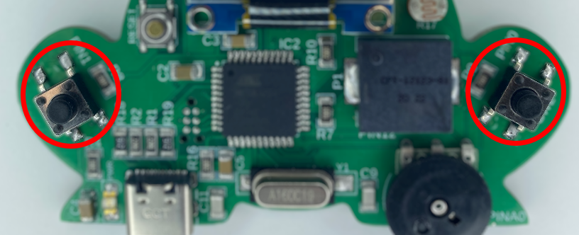
There are two buttons on the MC Trainer we can use, SW1 and SW2. SW1 is on the left side of the board and SW2 is on the right side. The abbreviation “SW” stands for switch.
Project Code:
////////////////////////////////////////////////////
// 3.00 - Read Input
byte SW1 = 1;

void setup() {
  Serial.begin(9600);
  pinMode(SW1, INPUT);
}

void loop() {
  bool buttonState = digitalRead(SW1);
  Serial.print("The state of the button is: "); Serial.println(buttonState);
  delay(250);
}
////////////////////////////////////////////////////
*If you’re copying and pasting the code, or typing from scratch, delete everything out of a new Arduino sketch and paste / type in the above text.
SW1 is connected to pin 1 so we first create a variable to represent our button in code:
byte SW1 = 1;
Next, in setup(), we initialize Serial so we can get feedback from our microcontroller:
Serial.begin(9600);
Then because we are trying to read something from the outside world (a button press), SW1 is an input.
pinMode(SW1, INPUT);
If you think about a button, it is either pressed or not pressed, there is no in-between. In similar terms, it is HIGH or LOW, ON or OFF, TRUE or FALSE, 1 or 0. A bool type variable is strictly meant to hold values like this, 1 or 0. So to store our buttons current state we will use a bool type variable.
bool buttonState
The digitalRead function can be used to read the digital state of a pin. This function will return a 1 if the voltage is HIGH (the button is not pressed) and a 0 if the voltage is LOW (the button is pressed).
bool buttonState = digitalRead(SW1);
Once read, the state of the button is printed out to the Serial port. Make sure to open it so you can see what is being printed!
Serial.print("The state of the button is: "); Serial.println(buttonState);
Lastly, there is a delay so thousands of lines don’t print out at once and the loop() is ended.
  delay(250);
}
Press SW1 and watch the button state change in the Serial monitor!
Now that we can read the button state, we can combine that with programmatic logic to make decisions on what to do when the button is pressed!
Project 2.01 Talking to the Board
In this project, you'll learn how to create a two-way communication channel between your Arduino board and the Serial Monitor on your computer!
In the last project the MC Trainer sent messages to the computer using Serial. In this project we will do the opposite! We can also use the Serial Port to send messages to the MC Trainer! These messages will pop up in the Serial port when you type them in and send them.
Project Code:
////////////////////////////////////////////
// 2.01 - Talking to the board

void setup() {
  Serial.begin(9600);
}

void loop() {
  while (Serial.available() == 0) {
    ;
  }

  byte messageSize = Serial.available();
  char message[messageSize];

  for (byte i = 0; i < messageSize; i++) {
    message[i] = Serial.read();
  }

  Serial.print("Message sent: "); Serial.println(message);
}
////////////////////////////////////////////
*If you’re copying and pasting the code, or typing from scratch, delete everything out of a new Arduino sketch and paste / type in the above text.
There are a few simple steps when we want to use the computer to communicate to the MC Trainer. Firstly, we must wait for Serial data to be sent from the Serial Port. The Serial.available() method will return the amount of data available from the Serial Port.
Let’s take a look at another kind of loop. In this program we use what’s called a while-loop. This kind of continuously runs while the conditional is true. See the table below for a breakdown of the while-loop used in the program:
| Type | while-loop |
|---|---|
| Conditional | Serial.available() == 0 |
| Code executed | ; |
The goal for the following lines of code is to keep us waiting in one spot in the program until we receive Serial data from the computer.
Serial.available() returns the amount of Serial data available to read from the computer. When it returns 0, that means there is no data to read. So, while there is no data to read, execute the code inside of the brackets “{}”.
The code inside of the brackets Is just a semi-colon. This essentially does nothing but take up some time. It’s an easy way to wait until something happens to move on. We are stuck in this while-loop (doing nothing) until our condition is met.
  while (Serial.available() == 0) {
    ;
  }
The next thing we need to do (After we’re out of the while-loop, meaning a message has been sent from the Serial port) is create a variable that can hold the incoming message. This will be an array of variable type char because char type variables hold a character. Using an array will allow us to store multiple characters in a convenient way.
How will we know how to size our array? In other words, how will we know how many spots our array needs for the incoming message? For that, we can use Serial.available() again. Remember that Serial.available() returns the amount of Serial data that is available to read. We can assign this returned value to a byte type for later use.
byte messageSize = Serial.available();
Once we know the size of the message, we create a character array to hold that message. First, we make the array type “char”, then name it “message”, then we size it with the variable we made earlier “[messageSize]”.
char message[messageSize];
Let’s do an example. Let’s say our message is “Hello”. What you have to know is that although it looks like there are only 5 characters that make up the word “Hello”, there are really six when it is sent over from the computer. There is ‘H’, ‘e’, ‘l’, ‘l’, ‘o’, and ‘\0’. The ‘\0’ is called a NULL terminator and signifies the end of a string of text.
Serial.available() will return the number 6 (Indicating that there are 6 characters to be read) and we can now create a variable to hold all of the characters.
Now we have a character array with 6 empty spots. Next, we need to use the Serial.read() method to read the Serial data. This method will read one byte (character) at a time sequentially. That means that calling it once will return the first character of what is being sent over, calling it again will read the second, and so on. As the incoming message is being read it needs to be stored in the array we created earlier.
Since we stored the length of the message in the messageSize variable, we can tell a for-loop how many times it needs to loop to read the entire message. The for-loop loops as many times as the message is long, and puts the characters read into the message array. We use the variable i to keep track of our spot in the array.
for (byte i = 0; i < messageSize; i++) {
    message[i] = Serial.read();
}
Visualized is the character array below when the for-loop finishes with the example “Hello” (Arrays start at Index 0):
| Index | 0 | 1 | 2 | 3 | 4 | 5 |
| Character | H | e | l | l | o | /0 |
Once the message is stored into the array, it is printed.
  Serial.print("Message sent: "); Serial.println(message);
}
////////////////////////////////////////////
To send data to the MC Trainer you first have to open the Serial monitor. Once the monitor is open, the text box at the top of it can be used to send a message. All you need to do is type in a message and hit the enter button. The computer will then attempt to send the message over Serial.
Project 2.00 Serial Printing
In this project, you'll learn how to utilize the Arduino's Serial communication capabilities to print text data to your computer's Serial Monitor!
In this project you will be introduced to Serial. Serial is a great way to see what is happening while your projects are running. Serial allows you to print strings of text, numbers and more out into a “Serial Port”. To open the Serial Port, click the magnifying glass in the top right of the Arduino IDE, or press ctrl + shift + m.
Here is what the magnifying glass will look like:

When you open the Serial port, it will appear in a window at the bottom of the screen. This is where the things you print will be displayed. Make sure to change this to “Newline” if it’s not already.
Project Code:
/////////////////////////////////////////////////
// 2.00 - Serial Printing

void setup() {
  Serial.begin(9600);
}

void loop() {
  Serial.print("My name is: ");
  Serial.println("YourNameHere");
  delay(1000);
}
/////////////////////////////////////////////////
*If you’re copying and pasting the code, or typing from scratch, delete everything out of a new Arduino sketch and paste / type in the above text.
This line initializes the Serial port for communication. The 9600 value passed is the “Baud rate”. Baud rate is the rate of bits transmitted per second. Because our microcontroller has a built-in USB interface, the number we pass here does not matter.
Serial.begin(9600);
There are a few common ways to print information to this screen. We can use the Serial.print and/or Serial.println methods.
The difference is that the Serial.println method will print a new line after it prints what was passed to it. It is important to note that if the data being printed is a string of characters, they need to be enclosed in quotations. If it is a single character, it can be enclosed in quotations or apostrophes. Otherwise, numbers and variables do not need to be enclosed in anything special.
  Serial.print("My name is: ");
  Serial.println("YourNameHere");
Change out the “YourNameHere” string with your name (enclosed in quotation marks).
Try making them both just Serial.print and see what happens!
A delay is needed to keep our MC Trainer from printing thousands of lines of text in a few seconds!
delay(1000);
Make sure and open the Serial port to see what is being printed!
Project 1.04 Pulse LED
In this project you’ll learn how to use the analogWrite function to create a “pulsing” effect on an LED!
This project demonstrates the full range of the analogWrite function, and how that can be used to create a pulsing effect.
Project Code:
/////////////////////////////////////////////////
// 1.04 - Pulse LED

byte LED1 = 13;

void setup() {
  pinMode(LED1, OUTPUT);
}

void loop() {
  byte wait = 10;

  for (int i = 0; i < 255; i++) {
    analogWrite(LED1, i);
    delay(wait);
  }

  for (int i = 255; i > 0; i--) {
    analogWrite(LED1, i);
    delay(wait);
  }
}
/////////////////////////////////////////////////
*If you’re copying and pasting the code, or typing from scratch, delete everything out of a new Arduino sketch and paste / type in the above text.
Before we jump into the code let’s take a look at what a for-loop is. A for-loop is a way to repeat a chunk of code a specified number of times. See the table below for a breakdown of a for-loop structure:
| Part | Description |
|---|---|
| for | Loop type |
| i < 255; | This is a conditional. The for-loop will continue to run while this is true. In this case, i is less than 255 |
| i++ | This increments the i variable by 1 every time the loop executes |
{
    analogWrite(LED1, i);
    delay(wait);
} |
This is the code that runs every time the loop executes |
for-loops can be a foreign concept. For a video explanation please visit:
https://www.youtube.com/watch?v=b4DPj0XAfSg
Here in the program a for-loop is used to count 0 – 255, slowly increasing the brightness of the LED. The index of the for-loop ( i ) is passed to the analogWrite function as the for-loop loops. A small delay is added after each analogWrite so the changes can be perceived by the human eye.
for (int i = 0; i < 255; i++) {
  analogWrite(LED1, i);
  delay(wait);
}
Here the program counts down 255 – 0, slowly decreasing the brightness of the LED.
for (int i = 0; i < 255; i++) {
  analogWrite(LED1, i);
  delay(wait);
}
Project 1.03 Analog Write
In this project, you will learn about a new function called analogWrite!
In this project you will learn about a new function called analogWrite. This function is useful for setting the brightness of LEDs. It can also be used to set the speed of motors, servo motor position, generating audio tones, and more.
The MC Trainer can only produce values of 0v and 5v but what happens when you need 2.5v? Simply put, the MC trainer cannot produce 2.5v. Instead, what it can do is switch a pin between 0v and 5v very quickly and produce an average voltage of 2.5v. This process is known as PWM.
It is important to note that this can only be done with certain pins. In our case, LED1 and LED2 can be used to do PWM.
This also introduces the Idea of duty cycle. Duty cycle is the ratio of how long a signal is on VS how long a signal is off. In this case the duty cycle would be 50%.
Project Code:
/////////////////////////////////////////////////
// 1.03 - Analog Write

byte LED1 = 13;

void setup() {
  pinMode(LED1, OUTPUT);
  analogWrite(LED1, 127);
}

void loop() {

}
/////////////////////////////////////////////////
*If you’re copying and pasting the code, or typing from scratch, delete everything out of a new Arduino sketch and paste / type in the above text.
The analogWrite function takes an 8-bit value between 0 – 255. 0 represents 0v and 255 represents 5v. The average voltage produced by that pin can be calculated with the equation: (analogValue * 5) / 255, with analogValue being the 8-bit number passed to the analogWrite function. For example, (127 * 5) / 255 = 2.49V. So, 127 will produce 2.49 volts.
analogWrite(LED1, 127);
When you run the code, the LED will be at half brightness.
Use the simulator below to explore different duty cycles!
Project 1.02 Simple LED Chase
In this project, you’ll use all four LEDs to blink a chase pattern!
In this project we will use all four LEDs to blink a chase pattern. This example shows a very simple way to create a pattern using digitalWrites and delays.
Project Code:
/////////////////////////////////////////////////
// Project 1.02 LED Chase

byte LED1 = 13;
byte LED2 = 6;
byte LED3 = 7;
byte LED4 = 8;

void setup() {
  pinMode(LED1, OUTPUT);
  pinMode(LED2, OUTPUT);
  pinMode(LED3, OUTPUT);
  pinMode(LED4, OUTPUT);
}

void loop() {
  digitalWrite(LED4, LOW);
  digitalWrite(LED1, HIGH);
  delay(250);
  digitalWrite(LED1, LOW);
  digitalWrite(LED2, HIGH);
  delay(250);
  digitalWrite(LED2, LOW);
  digitalWrite(LED3, HIGH);
  delay(250);
  digitalWrite(LED3, LOW);
  digitalWrite(LED4, HIGH);
  delay(250);
}
/////////////////////////////////////////////////
*If you’re copying and pasting the code, or typing from scratch, delete everything out of a new Arduino sketch and paste / type in the above text.
Here we set the four variables needed to represent the pins that the LEDs are attached to:
byte LED1 = 13;
byte LED2 = 6;
byte LED3 = 7;
byte LED4 = 8;
Next, we need to tell the microcontroller that these pins are outputs:
void setup() {
  pinMode(LED1, OUTPUT);
  pinMode(LED2, OUTPUT);
  pinMode(LED3, OUTPUT);
  pinMode(LED4, OUTPUT);
}
After that, we can sequentially turn on and off the LEDs to represent a chase pattern. To do this, we have to turn the last LED off, the next LED on, and then wait.
void loop() {
  digitalWrite(LED4, LOW);
  digitalWrite(LED1, HIGH);
  delay(250);
  digitalWrite(LED1, LOW);
  digitalWrite(LED2, HIGH);
  delay(250);
  digitalWrite(LED2, LOW);
  digitalWrite(LED3, HIGH);
  delay(250);
  digitalWrite(LED3, LOW);
  digitalWrite(LED4, HIGH);
  delay(250);
}
What you may have noticed about the code above is that something happened over and over again. Usually, when things happen over and over again, it is a sign that it should be in some kind of loop and/or function.
Project 1.01 Blink x2
In this project, you’ll learn how to blink more than one LED!
In this project, we bring a second LED, LED3, into the mix. We are essentially doing the same thing as the last project, but this time we are using two LEDs.
Project Code:
///////////////////////////////////////////////////
//Project 1.01 Blink x 2
byte LED1 = 13;
byte LED3 = 7;

void setup(){
  pinMode(LED1,OUTPUT);
  pinMode(LED3,OUTPUT);
}

void loop(){
  digitalWrite(LED1,HIGH);
  digitalWrite(LED3,HIGH);
  delay(1000);
  digitalWrite(LED1,LOW);
  digitalWrite(LED3,LOW);
  delay(1000);
  digitalWrite(LED1,HIGH);
  digitalWrite(LED3,LOW);
  delay(1000);
  digitalWrite(LED1,LOW);
  digitalWrite(LED3,HIGH);
  delay(1000);
  digitalWrite(LED1,LOW);
  digitalWrite(LED3,LOW);
  delay(1000);
}
///////////////////////////////////////////////////
*If you’re copying and pasting the code, or typing from scratch, delete everything out of a new Arduino sketch and paste / type in the above text.
Like all sketches, this simple sketch includes a setup() and a loop() function. Before the setup() function, we declare two variables that refer to the pin numbers for LED1 and LED3:
byte LED1 = 13;
byte LED3 = 7;
In the setup() function, we set both pins to OUTPUT using two pinMode statements:
pinMode(LED1,OUTPUT);
pinMode(LED3,OUTPUT);
In the loop() function, we first switch both LEDs on by setting the pins to HIGH using two digitalWrite statements:
void loop(){
  digitalWrite(LED1,HIGH);
  digitalWrite(LED3,HIGH);
  delay(1000);
After a 1-second delay, we turn both LEDs off:
digitalWrite(LED1,LOW);
digitalWrite(LED3,LOW);
delay(1000);
Next, we turn only LED1 on:
digitalWrite(LED1,HIGH);
digitalWrite(LED3,LOW);
delay(1000);
And then switch so that only LED3 is on:
digitalWrite(LED1,LOW);
digitalWrite(LED3,HIGH);
delay(1000);
Finally, we turn both LEDs off for 1 second before the loop() function reaches its closing bracket } and begins again at the top:
  digitalWrite(LED1,LOW);
  digitalWrite(LED3,LOW);
  delay(1000);
}
Project 1.00 Blink
In this project, you’ll learn how to blink an LED!

Nearly everyone starts by learning how to blink an LED. Let’s take a second to think about how a light blinks. First, a light turns on, then waits for some amount of time, then turns off, waits for some amount of time, and repeats. That process is what we need to create in Arduino code.
///////////////////////////////////////////////////
//Project 1.00 Blink

byte LED1 = 13;

void setup(){
  pinMode(LED1,OUTPUT);
}

void loop(){
  digitalWrite(LED1,HIGH);
  delay(1000);
  digitalWrite(LED1,LOW);
  delay(1000);
}
///////////////////////////////////////////////////
*If you’re copying and pasting the code, or typing from scratch, delete everything out of a new Arduino sketch and paste / type in the above text.
Let’s take a closer look at how this sketch works. We declare one byte variable at the top of the sketch. It is a global variable since it is declared outside the setup() function, loop() function, or any other function. This means we can use it anywhere else in the sketch and it will be recognized. LED1 gets assigned the value 13 because that’s the pin number (on the microcontroller) that LED1 is connected to.
byte LED1 = 13;
Every sketch needs one setup() and one loop() function. The setup() function runs only once. That’s all we need to set the pinMode of the LED to output so that we can switch it on and off:
void setup(){
   pinMode(LED1,OUTPUT);
}
Now comes the loop() function. This function will run repeatedly. At the top of the block comes the digitalWrite statement. This powers the pin attached to LED1 with 5 V, causing the LED to light up.
void loop(){
   digitalWrite(LED1,HIGH);
LED1 will remain in a HIGH state until we tell it otherwise or we disconnect the MC Trainer from its power source. We want it to stay on for only a second, so we wait 1000 milliseconds (1 second):
delay(1000);
And then switch the pin to LOW. Now the LED switches off:
digitalWrite(LED1,LOW);
We keep it off for another second and then finish the loop() function:
  delay(1000);
}
The closing bracket tells the MC Trainer to go back to the top of the loop() function and repeat it.
Try seeing how fast the LED can blink by changing the number in the delay function. Just a hint, it can blink faster than we can see!