

Project 12.00 Using the Board as a Keyboard
This Arduino sketch demonstrates how to use the MC Trainer as a keyboard input device!
The MCU trainer can also act like a keyboard!
Project Code:
//////////////////////////////////////////////////////
// 12.00 - Using the Board as a Keyboard

#include "Keyboard.h"

byte SW1 = 1;
bool pressed = LOW;

int pressCounter = 0;

void setup() {
  pinMode(SW1, INPUT);

  Keyboard.begin();
}

void loop() {
  while (digitalRead(SW1) != pressed) {
    ;
  }

  pressCounter++;

  Keyboard.print("You have pressed the button: ");
  Keyboard.print(pressCounter);
  Keyboard.println(" times!");

  delay(500);
}
//////////////////////////////////////////////////////
*If you’re copying and pasting the code, or typing from scratch, delete everything out of a new Arduino sketch and paste / type in the above text.
Just like the previous project, we need to put the keyboard on some kind of control. We don’t want thousands of keypresses being sent to the computer at a time!
Also like the other project, to use the keyboard functionality we need to include a library that comes with the Arduino IDE by default. We can do that by simply typing in “ #include "Keyboard.h".
#include "Keyboard.h"
We then use some standard variables to represent the button.
byte SW1 = 1;
byte pressed = LOW;
In this program we are also going to use a variable to keep track of the number of times the button has been pressed.
int pressCounter = 0;
Then in the setup() function, all we need to do is set the correct pinMode for the button pin and initialize the keyboard with the Keyboard.begin() function.
void setup() {
  pinMode(SW1, INPUT);

  Keyboard.begin();
}
In the loop() function, the first thing we do is wait until the button is pressed.
void loop() {
  while (digitalRead(SW1) != pressed) {
    ;
   }
When the button is pressed, the program moves on from the while-loop. Since the button has been pressed, we increment the pressCounter variable.
pressCounter++;
After that we can use the MCU Trainer to type that information out onto the screen. The print and println functions here work exactly the same as the Serial versions.
Keyboard.print("You have pressed the button: ");
Keyboard.print(pressCounter);
Keyboard.println(" times!");
A crude debounce is then implemented to keep the button from being read too many times.
  delay(500);
}
//////////////////////////////////////////////////////
To see the text being printed out open a text editor, click on the screen, and press the button.
You have pressed the button: 1 times!
You have pressed the button: 2 times!
You have pressed the button: 3 times!
You have pressed the button: 4 times!
You have pressed the button: 5 times!
You have pressed the button: 6 times!
You have pressed the button: 7 times!
You have pressed the button: 8 times!
You have pressed the button: 9 times!
You have pressed the button: 10 times!
Project 11.00 Using the Board as a Mouse
This Arduino sketch demonstrates how to use the MC Trainer board as a mouse input device!
The MCU trainer can also act like a mouse on a computer! This functionality is unique with microcontrollers. In this project you’ll learn how to use it as such!
Project Code:
//////////////////////////////////////////////////////
// 11.00 - Using The Board As A Mouse

#include "Mouse.h"

byte SW1 = 1;
byte pressed = LOW;

void setup() {
  pinMode(SW1, INPUT);

  Mouse.begin();
}

void loop() {
  if (digitalRead(SW1) == pressed) {

    for (byte x = 0; x < 100; x++) {
      Mouse.move(1, 0, 0);
    }

    for (byte x = 0; x < 100; x++) {
     Mouse.move(0, 1, 0);
    }

    for (byte x = 0; x < 100; x++) {
      Mouse.move(-1, 0, 0);
    }

    for (byte x = 0; x < 100; x++) {
      Mouse.move(0, -1, 0);
    }
  }

  //You can also:
  /*
    Click the mouse:
    Mouse.press(MOUSE_RIGHT);
    Mouse.press(MOUSE_MIDDLE);
    Mouse.press(MOUSE_LEFT);

    Release the mouse:
    Mouse.release(MOUSE_RIGHT);
    Mouse.release(MOUSE_MIDDLE);
    Mouse.release(MOUSE_LEFT);

  */
}
//////////////////////////////////////////////////////
*If you’re copying and pasting the code, or typing from scratch, delete everything out of a new Arduino sketch and paste / type in the above text.
Before you write a program that includes mouse functionality it is important to be able to control it. In this project we don’t activate the mouse functionality unless a button is pressed. When you plug the MCU Trainer in, you don’t want your mouse going crazy!
The first thing that we need to do is include the proper library. There is no need to install this library as it comes standard with the Arduino IDE. All you’d have to do is type in “ #include “Mouse.h”.
#include "Mouse.h"
Next, we need to include some variables to be used with the button.
byte SW1 = 1;
byte pressed = LOW;
In the setup() function, we need to set the pinMode of the button and initialize the mouse functionality. Initializing the MCU Trainer as mouse can be done with the Mouse.begin() method.
void setup() {
  pinMode(SW1, INPUT);

  Mouse.begin();
}
In the loop() function, we check to see if the button has been pressed before using the mouse functionality.
void loop() {
  if (digitalRead(SW1) == pressed) {
Once SW1 has been pressed, we can use the Mouse.move method to move the mouse! The first parameter is how many pixels to move in the x direction, the second is how many pixels to move in the y direction and the last is how many lines to scroll. The mouse will move instantly so it has been put into a series of for-loops and run a certain number of times to make incremental changes instead (So we can see it change).
for (byte x = 0; x < 100; x++) {
  //         x  y  scroll
  Mouse.move(1, 0, 0);
}

for (byte x = 0; x < 100; x++) {
  //         x  y  scroll
  Mouse.move(0, 1, 0);
}
To move in the opposite direction all you have to do is pass it a negative value.
for (byte x = 0; x < 100; x++) {
  //         x  y  scroll
  Mouse.move(-1, 0, 0);
}

for (byte x = 0; x < 100; x++) {
    Mouse.move(0, -1, 0);
  }
}
Here are some additional functions you can use with the Mouse.h library:
  //You can also:
  /*
    Click the mouse:
    Mouse.press(MOUSE_RIGHT);
    Mouse.press(MOUSE_MIDDLE);
    Mouse.press(MOUSE_LEFT);

    Release the mouse:
    Mouse.release(MOUSE_RIGHT);
    Mouse.release(MOUSE_MIDDLE);
    Mouse.release(MOUSE_LEFT);

  */
}
//////////////////////////////////////////////////////
Project 10.01 Sending IR
In this project, you'll discover how to transmit infrared (IR) data using the MC Trainer and the IRremote library!
This project aims to replicate the functionality of an IR remote control. We'll be using a push-button switch to trigger the sending of specific IR signals, which can be read by an IR receiver. This can be used to do things like turn on a TV!
Project Code:
//////////////////////////////////////
// 10.01 Sending Data

#include <IRremote.h>

byte sCommand = 0x9;
byte ADDR = 0x0;

byte SW1 = 1;
bool pressed = 0;

byte IRPin = 5;

void setup() {
  Serial.begin(9600);
  IrSender.begin(IRPin);
  pinMode(SW1, INPUT);
}

void loop() {
  if (digitalRead(SW1) == pressed) {
    Serial.println();
    Serial.print("Send now: address=0x");
    Serial.print(ADDR, HEX);
    Serial.print(", command=0x");
    Serial.println(sCommand, HEX);

    IrSender.sendNEC(ADDR, sCommand, 0);

    delay(250);
  }
}
//////////////////////////////////////
*If you’re copying and pasting the code, or typing from scratch, delete everything out of a new Arduino sketch and paste / type in the above text.
In the setup() function, the IR emitter is started on pin 5 using IrSender.begin(IRPin).
IrSender.begin(IRPin);
In the loop() function, SW1 is monitored to see if it has been pressed.
if (digitalRead(SW1) == pressed) {
If the button has been pressed, information about what is being sent is printed using the Serial methods. You’ll notice that some of the Serial.print methods have two parameters. You can use keywords such as DEC, HEX, BIN, OCT to print numbers in a specific number base. Data used with the IR protocol is generally in hexadecimal, so we print it in that fashion with the HEX keyword.
Serial.println();
Serial.print("Send now: address=0x");
Serial.print(ADDR, HEX);
Serial.print(", command=0x");
Serial.println(sCommand, HEX);
Next, the data is actually sent with the IrSender.sendNEC method. There are three parameters to this method. The first parameter is the address that the data should be sent to, the second parameter is the data to be sent, and the last parameter is the number of times the data should be repeated. Sometimes it is useful to repeat the signal a few times to ensure it makes it to the intended device.
IrSender.sendNEC(ADDR, sCommand, 0);
What if the data is not the NEC protocol? This library supports a wide range of protocols. They are listed here:
| Protocol | Method |
|---|---|
| NEC | IrSender.sendNEC() |
| Sony | IrSender.sendSony() |
| RC5 | IrSender.sendRC5() |
| RC6 | IrSender.sendRC6() |
| Dish | IrSender.sendDISH() |
| JVC | IrSender.sendJVC() |
| Samsung | IrSender.sendSAMSUNG() |
| LG | IrSender.sendLG() |
| Whynter | IrSender.sendWhynter() |
| COOLIX | IrSender.sendCOOLIX() |
| Denon | IrSender.sendDenon() |
| Sharp | IrSender.sendSharpRaw() |
| Panasonic | IrSender.sendPanasonic() |
| Sanyo | IrSender.sendSanyo() |
| Mitsubishi | IrSender.sendMitsubishi() |
| Apple | IrSender.sendApple() |
| Pronto | IrSender.sendPronto() |
| LEGO Power Functions | IrSender.sendLegoPowerFunctions() |
| Bose Wave | IrSender.sendBoseWave() |
| Metz | IrSender.sendMetz() |
| MagiQuest | IrSender.sendMagiQuest() |
| RCMM | IrSender.sendRCMM() |
Some of these methods may take different parameters so consult the library reference, or simply Google it before using.
The loop is then ended with a delay if the button was pressed as a crude debounce.
    delay(250);
  }
}
//////////////////////////////////////
Project 10.00 Decoding IR
This Arduino sketch demonstrates how to use an Infrared (IR) receiver module to receive and decode IR remote control signals!

This Arduino sketch is designed to receive and decode infrared signals. When you point a remote at the MCU Trainer, the decoded results are printed to the Serial Monitor.
Project Code:
///////////////////////////////////////////
// 10.00 Infrared Receiver

#include <IRremote.h>

byte IRRecv = 17;

void setup() {
  Serial.begin(9600);
  IrReceiver.begin(IRRecv);
}

void loop() {
  if (IrReceiver.decode()) {
    IrReceiver.printIRResultShort(&Serial);
    IrReceiver.resume();
  }
}
///////////////////////////////////////////
*If you’re copying and pasting the code, or typing from scratch, delete everything out of a new Arduino sketch and paste / type in the above text.
Before we do anything, we need to install the IRremote Library. You can do this by going to Tools -> Manage Libraries, and type in “IRremote”. It looks like this:

Click install. If it asks you to install dependencies go ahead and do so.
For reference, you can include it into a project by going to Sketch -> Include Library, and click “IRremote”. This does not need done in this sketch as it is already included.
The library reference where you can find all of the functions avaliable can be found here:
https://github.com/Arduino-IRremote/Arduino-IRremote
In the setup() function we initialize the IR receiver on digital pin 17 using the begin() method from the IRremote library.
IrReceiver.begin(IRRecv);
The loop() function continuously checks for incoming IR signals. It uses the decode() method to check if a signal has been received. If a signal has been received the decode() method then returns a one and the if-statement code executes.
if (IrReceiver.decode())
If a signal is received, it then prints a short summary of the decoded data to the Serial Monitor using the printIRResultShort function. The data printed includes the protocol used, the address, command, and raw data. Much like the “&Wire” don’t worry too much about what the “&Serial” that we pass is really doing. Just know we need to pass that to print out the data.
IrReceiver.printIRResultShort(&Serial);
It then resumes the receiver to keep listening for new signals using the resume() function.
    IrReceiver.resume();
  }
}
///////////////////////////////////////////
Make sure and open the Serial monitor to see what is being printed.
Now that you can see what the signal that your remote is sending, you can use the IR emitter to copy that signal.
The data that I got from my remote was:
“Protocol=NEC Address=0x0 Command=0x9 Raw-Data=0xF609FF00 32 bits LSB first”
Let’s break that data down:
| Section | Description |
|---|---|
| Protocol=NEC | This means the infrared signal uses the NEC protocol, a common infrared protocol used in consumer electronics. |
| Address=0x0 | The address is used to specify the target device that should respond to this signal. In this case, the address is 0x0, which usually indicates a generic device. |
| Command=0x9 | The command portion of the signal tells the device what to do. In this case, the command is 0x9. |
| Raw-Data=0xF609FF00 | This represents the raw data of the signal received by the IR receiver. This is typically a sequence of pulse and space lengths that make up the actual signal. The raw data is useful for debugging or for cases where the protocol, address, and command don't adequately represent the signal. |
| 32 bits LSB first | This indicates that the data is 32 bits long and that it's being read from the least significant bit (LSB) first. This is important for correctly interpreting the raw data. |
We can use this data to emulate the remote with the IR emitter LED.
Project 9.02 Doing Something Based on Temperature
In this project, you'll learn how to create a dynamic temperature-responsive display using the MC Trainer!
In this project we will use the temperature data to change the color of the Neopixels based on the temperature. The warmer the temperature to more red the Neopixels will appear. The colder the temperature sensor the more blue the Neopixels will appear.
Project Code:
//////////////////////////////////////////////////////
// 9.02 - Doing Something Based on Temperature

#include <Adafruit_NeoPixel.h>

byte dataPin = 10;
byte numberOfPixels = 2;
byte brightness = 10;

byte redValue = 0;
byte greenValue = 0;
byte blueValue = 0;

byte tempSensorPin = A3;

Adafruit_NeoPixel pixels(numberOfPixels, dataPin, NEO_GRB + NEO_KHZ800);
void setup() {
  pinMode(tempSensorPin, INPUT);

  pixels.begin();
  pixels.setBrightness(brightness);

  Serial.begin(9600);
}

void loop() {

  float currentTemperature = ReadTemperature();

  Serial.print("The temp in C is: "); Serial.println(currentTemperature);
  Serial.print("The temp in F is: "); Serial.println(CtoF(currentTemperature));

  UpdatePixelColorBasedOnTemp(CtoF(currentTemperature));
  delay(1000);

}

/*
   This function takes a temperature in degrees F and updates the neopixels to reflect the temperature.
   The hotter the temperature, the more red the neopixels.
   The colder the temperature, the more blue the neopixels.
*/
void UpdatePixelColorBasedOnTemp(float temperature) {

  int blueValue = map(temperature, 70, 80, 255, 0);
  blueValue = constrain(blueValue, 0, 255);

  int redValue = map(temperature, 70, 80, 0, 255);
  redValue = constrain(redValue, 0, 255);

  Serial.print("Blue: "); Serial.println(blueValue);
  Serial.print("Red: "); Serial.println(redValue);

  pixels.setPixelColor(0, pixels.Color(redValue, 0, blueValue));
  pixels.setPixelColor(1, pixels.Color(redValue, 0, blueValue));
  pixels.show();
}

/*
   This function reads a temperature in degrees C from the MCP9700AT-E/TT and returns it.
*/
float ReadTemperature() {
  int currentTempReading = analogRead(tempSensorPin);

  float currentTempVoltage = currentTempReading * (5.0 / 1024.0);
  float temperature = (currentTempVoltage - .5) /  .01;

  return (temperature);
}

/*
   This function converts a temperature passed in degrees C to degrees F and returns it.
*/
float CtoF(float temp) {
  return ((temp * 1.8) + 32);
}
//////////////////////////////////////////////////////
*If you’re copying and pasting the code, or typing from scratch, delete everything out of a new Arduino sketch and paste / type in the above text.
This project is fairly simple thanks to the functions we wrote in the last project. They are simply copied and pasted into this one.
The first thing that we need to do is include the Neopixel library.
#include <Adafruit_NeoPixel.h>
Next, we declare some standard variables and include the constructor for the Neopixel library.
byte dataPin = 10;
byte numberOfPixels = 2;
byte brightness = 10;

byte redValue = 0;
byte greenValue = 0;
byte blueValue = 0;

byte tempSensorPin = A3;

Adafruit_NeoPixel pixels(numberOfPixels, dataPin, NEO_GRB + NEO_KHZ800);
After that in the setup() function, we set the pinMode of the analog pin connected to the temperature sensor, initialize the Neopixels, and setup Serial communication.
void setup() {
  pinMode(tempSensorPin, INPUT);

  pixels.begin();
  pixels.setBrightness(brightness);

  Serial.begin(9600);
}
The loop() function starts just like the last project did. First, we get the current temperature.
void loop() {

  float currentTemperature = ReadTemperature();
Next, the temperature is printed out in Celsius and Fahrenheit.
Serial.print("The temp in C is: "); Serial.println(currentTemperature);
Serial.print("The temp in F is: "); Serial.println(CtoF(currentTemperature));
Let’s take a look at the next function in the loop(), “UpdatePixelColorBasedOnTemp”. From the function description we know that this function takes a temperature in degrees Fahrenheit and updates the Neopixels to reflect that temperature. This is why the temperature is passed to the function with the CtoF function.
UpdatePixelColorBasedOnTemp(CtoF(currentTemperature));
Inside the function we can see what is really happening. First the blue value is mapped to the temperature range of 70 – 80 degrees F.
The parameters in this implementation of the map function are a bit different than usual. You’ll see that the higher end of the output range is mapped to the lower end of the temperature range, and vice versa. This means that when the temperature is 70 degrees the output will be 255 and when the temperature is 80 degrees the output will be 0. This is an easy way to invert the output range to go from high to low. We need this because as the temperature gets lower, we want a larger blue value.
int blueValue = map(temperature, 70, 80, 255, 0);
Then the constrain function is used to ensure we stay in the proper output range.
blueValue = constrain(blueValue, 0, 255);
Next, we will use the map function normally to map the temperature range to the red output range. The constrain function is used to keep the values in the proper range.
int redValue = map(temperature, 70, 80, 0, 255);
redValue = constrain(redValue, 0, 255);
Then these values are printed out onto the Serial port.
Serial.print("Blue: "); Serial.println(blueValue);
Serial.print("Red: "); Serial.println(redValue);
After that the Neopixels are loaded and updated.
  pixels.setPixelColor(0, pixels.Color(redValue, 0, blueValue));
  pixels.setPixelColor(1, pixels.Color(redValue, 0, blueValue));
  pixels.show();
}
Going back to the loop() funciton, after the UpdatePixelColorBasedOnTemp function, a small delay is implemented to keep the Serial port from flooding and the loop() is ended.
  delay(1000);

}
Project 9.01 Getting an Actual Temperature Reading
This Arduino sketch reads the analog value from the temperature sensor connected to analog pin A3 and converts it into actual temperature readings in both Celsius (°C) and Fahrenheit (°F) using functions for reading the temperature and performing the conversion!
In this project you’ll learn how to convert the analog value read from the sensor into an actual temperature. This can get a bit complicated but it’s how many sensors work in the real world.
Project Code:
//////////////////////////////////////////////////////
// 9.01 - Getting an Actual Temperature Reading

byte tempSensorPin = A3;

void setup() {
  pinMode(tempSensorPin, INPUT);
  Serial.begin(9600);

}

void loop() {

  float currentTemperature = ReadTemperature();

  Serial.print("The temp in C is: "); Serial.println(currentTemperature);
  Serial.print("The temp in F is: "); Serial.println(CtoF(currentTemperature));
  delay(1000);

}

/*
   This function reads a temperature in degrees C from the MCP9700AT-E/TT and returns it.
*/
float ReadTemperature() {
  int currentTempReading = analogRead(tempSensorPin);

  float currentTempVoltage = currentTempReading * (5.0 / 1024.0);

  float temperature = (currentTempVoltage - .5) /  .01;

  return(temperature);
}

/*
   This function converts a temperature passed in degrees C to degrees F and returns it.
*/
float CtoF(float temp) {
  return ((temp * 1.8) + 32);
}
//////////////////////////////////////////////////////
*If you’re copying and pasting the code, or typing from scratch, delete everything out of a new Arduino sketch and paste / type in the above text.
Before we look at the code let’s figure out how we are going to go about getting an actual temperature reading. The first thing that we need to find is the equation for converting the analog value read to a temperature. This can be found in the datasheet for the part on page 10.
https://www.mouser.com/datasheet/2/268/MCP9700_Family_Data_Sheet_DS20001942-3132871.pdf
Datasheets can be very intimidating, even for seasoned engineers. Take a look at the datasheet for the Atmega32u4 (The chip you’re programming):
https://ww1.microchip.com/downloads/en/devicedoc/atmel-7766-8-bit-avr-atmega16u4-32u4_datasheet.pdf
It’s 438 pages!
The equation on page 10 states:
Vout = Tc * Ta + V0degreesC
Let’s break that down:
| Symbol | Description |
|---|---|
| Vout | Voltage produced by the temperature sensor |
| Tc | Temperature Coefficient |
| Ta | Ambient Temperature |
| V0degreesC | Voltage produced at 0 degrees C |
So, what do we know? Only the voltage read right now. Let’s go back to the datasheet.
On page 4 we can find the temperature coefficient (10mV per degree C), on page 3 we can find the V0degreesC (500mV) and what we are trying to figure out is the ambient temperature.
Now we know the voltage being read (with analogRead), the temperature coefficient, and the V0degrees, we can re-arrange the equation for ambient temperature:
Vout = Tc * Ta + V0degreesC
Vout – V0degreesC = Tc * Ta <- Subtracted V0degrees
(Vout – V0degreesC) / Tc = Ta <- Divided by Tc
Ta = (Vout – V0degreesC) / Tc <- Just re-written from #3
When we read the analog voltage value from the temperature sensor it will be a value between 0 – 1023. Unfortunately, that is in the wrong form for us. What we need is voltage, not a 10-bit value. In order to convert from a 10-bit number to the voltage it represents we can use the equation:
10bitValue * (5 / 1024)
For example, we would expect a value of about 2.5 with an analog value of 512:
512 * (5 / 1024) = ~2.5v
We can use this equation to convert from 10-bit to voltage.
Now that we have all of the tools we need let’s look at how to use them.
In the loop() function, we have created a variable of type float and assigned it the value that the function ReadTemperature() will return. All this does is run the function and assign the value it returns to the currentTemperature variable.
float currentTemperature = ReadTemperature();
In the ReadTemperature() function, we first take an analogRead of the temperature sensor pin.
int currentTempReading = analogRead(tempSensorPin);
After that we then convert that analog value read into a voltage and assign it to a variable of type float. You may notice the “.0” on the end of the numbers. This specifies these numbers as float type numbers. The number “5” is an int and the number “5.0” is a float. So, if we’re trying to do floating point math, we have to use the “.0” with our numbers. If we did “5 / 1023“ the result would be 0!
float currentTempVoltage = currentTempReading * (5.0 / 1023.0);
Next, we use the equation we re-arranged earlier to convert to an actual temperature. That value is assigned to a float type variable.
float temperature = (currentTempVoltage - .5) / .01;
Then that value is returned.
return(temperature);
Going back to the loop() funciton, we then Serial print the temperature value out in Celsius and Fahrenheit.
Serial.print("The temp in C is: "); Serial.println(currentTemperature);
Serial.print("The temp in F is: "); Serial.println(CtoF(currentTemperature));
The CtoF function is there to convert from Celsius to Fahrenheit.
/*
   This function converts a temperature passed in degrees C to degrees F and returns it.
*/
float CtoF(float temp) {
  return ((temp * 1.8) + 32);
}
A one second delay is used after the Serial prints to prevent flooding of the Serial port.
delay(1000);
Who knew reading temperature could be so complicated? Luckily, these functions we made can just be copied and pasted into other programs. This is why people create libraries!
Project 9.00 Using the Temp Sensor
This Arduino sketch reads the analog value from a temperature sensor connected to analog pin A3 and prints the temperature value (represented by the analog reading) to the serial monitor!

In this project you’ll learn how to read the voltage produced by the temperature sensor. The temperature sensor on the MC Trainer is tiny! It is the tiny black rectangle on the left of the OLED, above the reset button.
Project Code:
//////////////////////////////////////////////////////
// 9.00 - Using the Temperature Sensor

byte tempSensorPin = A3;

void setup() {
  pinMode(tempSensorPin, INPUT);
  Serial.begin(9600);
}

void loop() {
  int currentTemp = analogRead(tempSensorPin);

  Serial.print("The current temp value is: "); Serial.println(currentTemp);
  delay(1000);

}
//////////////////////////////////////////////////////
*If you’re copying and pasting the code, or typing from scratch, delete everything out of a new Arduino sketch and paste / type in the above text.
The temperature sensor works a lot like the potentiometer and LDR. The difference is that this temperature sensor actually produces a voltage based on the temperature. The potentiometer and LDR were dropping a certain amount of voltage based on some condition.
The temperature sensor again produces an analog voltage based on the temperature. This means that if we want to read that analog value it needs to be on an analog pin. The temperature sensor is connected to the analog pin A3 on the MC Trainer.
byte tempSensorPin = A3;
We are reading the voltage, so the pin is an INPUT.
pinMode(tempSensorPin, INPUT);
In the loop() function, we analog read the voltage produced by the temperature sensor.
int currentTemp = analogRead(tempSensorPin);
After that, we print it onto the Serial port. Make sure to open the Serial port to see the data being printed.
Serial.print("The current temp value is: "); Serial.println(currentTemp);
So that we don’t flood the screen we add in a one second delay.
delay(1000);
Try touching the temperature sensor and seeing how the values change.
Project 8.02 Mapping Light
This Arduino sketch reads the analog value from a light sensor connected to pin A2, maps it to a corresponding brightness level for an LED connected to pin 13 (LED1), and adjusts the LED brightness accordingly!
In this project we will use the Min and Max brightness values from the last sketch to vary the brightness of an LED based on the light on the LDR. The darker the room, the brighter LED1 will be.
Project Code:
//////////////////////////////////////////
// 8.02 Mapping Light

byte lightSensorPin = A2;
int maxValue = 909;
byte minValue = 23;

byte LED1 = 13;

void setup() {
  pinMode(lightSensorPin, INPUT);
  pinMode(LED1, OUTPUT);
  Serial.begin(9600);
}

void loop() {
  int currentValue = analogRead(lightSensorPin);

  int LED1Brightness = map(currentValue, minValue, maxValue, 0, 255);

  LED1Brightness = constrain(LED1Brightness, 0, 255);

  analogWrite(LED1, LED1Brightness);
}
//////////////////////////////////////////
*If you’re copying and pasting the code, or typing from scratch, delete everything out of a new Arduino sketch and paste / type in the above text.
In my case, my maxValue is 909 and my minValue is 23. Yours will probably be slightly different. You’ll need to update the variables below for your specific values.
int maxValue = 909;
byte minValue = 23;
In the loop() function, we first have to analogRead the voltage on the LDR. The analogRead function reads from 0 – 1023 (10-bit) but the analogWrite function write values of 0 – 255 (8-bit). The map function will take care of this issue. Remember, the map function takes five parameters. It takes the value to map, the min value of that range, the max value of that range, the min value of the range to be mapped to, and the max value of the range to be mapped to.
int LED1Brightness = map(currentValue, minValue, maxValue, 0, 255);
Sometimes the LDR will register values higher or lower than the range we defined in our code. For this reason, we want to “Constrain” our readings. This just keeps our readings from going above or below the range we’ve defined.
To keep this from happening, what we need to do is use the constrain function. The constrain function allows us to keep a variable in between certain numbers. For example, if we were to get a value of 300 and our constrain range is 0 – 255, the function would return 255. The same is true for the lower range, but it returns the low constrained value. If the value is instead within the range, it just returns that value.
LED1Brightness = constrain(LED1Brightness, 0, 255);
Lastly, the LED1Brightness analog value is written to LED1.
analogWrite(LED1, LED1Brightness);
Project 8.01 Max and Min Brightness
This Arduino sketch reads the light intensity from a light sensor connected to analog pin A2 and continuously monitors and updates the maximum and minimum brightness values observed!
In this project, we'll find out the real-world minimum and maximum readings from our Light Dependent Resistor (LDR) in the room you’re in. Unlike the potentiometer, in practice the LDR won't give us the full range from 0 to 1023 that we can read with the analogRead function.
Why is that? Well, our LDR is set up in a circuit in series another resistor, which has a resistance of 10,000 ohms. The readings we get depend on the total resistance of this setup.
For us to get a reading of 0, the LDR would have to have no resistance at all - that's 0 ohms, which isn't going to happen because all objects have some resistance.
Similarly, for us to get the maximum reading of 1023, the LDR would need to have an infinite amount of resistance. That's not possible either.
So, the real-world readings we get will be somewhere in between, and that's what we're going to find out!
Project Code:
///////////////////////////////////////////////
// 8.01 Max and Min Brightness

byte lightSensorPin = A2;
int maxValue = 0;
int minValue = 0;

void setup() {
  pinMode(lightSensorPin, INPUT);

  Serial.begin(9600);

  maxValue = analogRead(lightSensorPin);
  minValue = analogRead(lightSensorPin);
}

void loop() {
  int currentBrightness = analogRead(lightSensorPin);

  if (currentBrightness > maxValue) {
    maxValue = currentBrightness;
    Serial.print("The new max brightness is: "); Serial.println(maxValue);
  }

  if (currentBrightness < minValue) {
    minValue = currentBrightness;
    Serial.print("The new min brightness is: "); Serial.println(minValue);
  }
}
///////////////////////////////////////////////
*If you’re copying and pasting the code, or typing from scratch, delete everything out of a new Arduino sketch and paste / type in the above text.
We will need a variable to hold the min and max voltage values that come across the LDR.
int maxValue = 0;
int minValue = 0;
In the setup() function, we have to load these variables we created with analogRead values. The reason these variables need loaded with real analogRead values is because we do not want to load them initially with values more or less than their range will support.
What does that mean? For example, if the lowest in the range of 0 – 1023 that the LDR would read was 20, then if we loaded the minValue with 0 and checked to see if any value went below it, it would never happen.
If we instead load it with an analogRead then that is part of the range by default, since it is a reading of the voltage across the LDR.
maxValue = analogRead(lightSensorPin);
minValue = analogRead(lightSensorPin);
In the loop() function, we first analogRead the current voltage value of the LDR
int currentBrightness = analogRead(lightSensorPin);
After that, we then look to see if the value of the currentBrightness variable is greater than the value of the maxValue variable. If so, we have a new max value and the maxValue variable needs to be reassigned with the value of currentBrightness. Then we print that value for our records.
if (currentBrightness > maxValue) {
  maxValue = currentBrightness;
  Serial.print("The new max brightness is: "); Serial.println(maxValue);
}
We then do the same thing but with the minValue variable. If currentBrightness variable is less than the minValue variable, we reassign it with its value and print it.
if (currentBrightness < minValue) {
  minValue = currentBrightness;
  Serial.print("The new min brightness is: "); Serial.println(minValue);
}
Make sure and write these values down for the next project. These are the max and min brightness values for the room you’re in. Think of this project as calibrating your MC Trainer to get the most out of it.
Project 8.00 Light Sensor
This Arduino sketch reads the light intensity from a light sensor connected to analog pin A2 and prints the values to the serial monitor!

In this project you’ll learn what an LDR is and how to analogRead it to determine light intensity.
Project Code:
///////////////////////////////////////////////////
//8.00 - Reading Light Intensity

byte lightSensorPin = A2;

void setup() {
  pinMode(lightSensorPin, INPUT);
  Serial.begin(9600);
}

void loop() {
  Serial.print("The light level is at: ");
  Serial.println(analogRead(lightSensorPin));
  delay(1000);
}

///////////////////////////////////////////////////
*If you’re copying and pasting the code, or typing from scratch, delete everything out of a new Arduino sketch and paste / type in the above text.
Reading the LDR is exactly the same as reading the potentiometer.
The pin that is connected to the LDR is an analog pin.
byte lightSensorPin = A2;
The LDR is going to have an analog voltage, which is read using analogRead. It is then printed out onto the Serial monitor. Make sure and open the Serial port to see the data being printed.
Serial.print("The light level is at: "); Serial.println(analogRead(lightSensorPin));
There is then a delay to keep the Serial port from being flooded with messages.
delay(1000);
The LDR will read more voltage the darker it is. We can use this information to control outputs based on the light intensity.
Project 7.03 Drawing Shapes with the OLED
We can do more than just text on the OLED. In this project you’ll learn how to draw shapes too!
We can do more than just text on the OLED. In this project you’ll learn how to draw shapes too!
Project Code:
////////////////////////////////////////////////////
// 7.03 Drawing Shapes with the OLED

#include <Adafruit_SSD1306.h>

byte screenWidth = 128;
byte screenHeight = 64;
byte screenAddress = 0x3C;

Adafruit_SSD1306 display(screenWidth, screenHeight, &Wire);
void setup() {
  display.begin(SSD1306_SWITCHCAPVCC, screenAddress);
  display.setTextColor(SSD1306_WHITE);
}

void loop() {
  display.clearDisplay();
  display.drawPixel(63, 32, WHITE);
  display.display();
  delay(1000);

  display.clearDisplay();
  display.drawLine(0, 0, 63, 63, WHITE);
  display.display();
  delay(1000);

  display.clearDisplay();
  display.drawCircle(63, 31, 12, WHITE);
  display.display();
  delay(1000);

  display.clearDisplay();
  display.fillCircle(63, 32, 12, WHITE);
  display.display();
  delay(1000);

  display.clearDisplay();
  display.drawTriangle(63, 0, 96, 63, 32, 63, WHITE);
  display.display();
  delay(1000);

  display.clearDisplay();
  display.fillTriangle(63, 0, 96, 63, 32, 63, WHITE);
  display.display();
  delay(1000);

  display.clearDisplay();
  display.drawRect(10, 10, 107, 43, WHITE);
  display.display();
  delay(1000);

  display.clearDisplay();
  display.fillRect(10, 10, 107, 43, WHITE);
  display.display();
  delay(1000);
}
////////////////////////////////////////////////////
*If you’re copying and pasting the code, or typing from scratch, delete everything out of a new Arduino sketch and paste / type in the above text.
First, we include the library needed for the OLED.
#include <Adafruit_SSD1306.h>
Then we make some standard variables for the OLED to define screen width, height, and the I2C address.
byte screenWidth = 128; byte screenHeight = 64; byte screenAddress = 0x3C;
After that we use the constructor to make our display object.
Adafruit_SSD1306 display(screenWidth, screenHeight, &Wire);
Now we can set the OLED up in the setup() function.
void setup() {
  display.begin(SSD1306_SWITCHCAPVCC, screenAddress);
  display.setTextColor(SSD1306_WHITE);
}
Next, we can use specific functions to draw different shapes on the OLED! Don’t forget that (0,0) for the OLED is actually in the top left of the screen.
The first shape we will explore is actually just a point. We can draw points on the OLED with the function drawPixel. The first parameter is the X position, the second parameter is the Y position, and the last parameter is the color. All of these functions last parameter will be “WHITE” since this OLED can only display white.
void loop() {
  display.clearDisplay();
  display.drawPixel(63, 32, WHITE);
  display.display();
  delay(1000);
The next shape is a line. We can use the drawLine function. These parameters are the starting x position, starting y position, ending x position, ending y position, and the color.
display.clearDisplay();
display.drawLine(0, 0, 63, 63, WHITE);
display.display();
delay(1000);
The next shape is a circle. We can use the drawCircle function. These parameters are the x position, y position, circle radius, and color.
display.clearDisplay();
display.drawCircle(63, 31, 12, WHITE);
display.display();
delay(1000);
The next shape is also a circle. We can use the fillCircle function to draw a circle that is filled in. These parameters are the x position, y position, circle radius, and color.
display.clearDisplay();
display.fillCircle(63, 32, 12, WHITE);
display.display();
delay(1000);
The next shape is a triangle. We can use the drawTriangle function. This function takes a set of three points and draws lines connecting them. The parameters are x0, y0, x1, y1, x2, y2, and color.
display.clearDisplay();
display.drawTriangle(63, 0, 96, 63, 32, 63, WHITE);
display.display();
delay(1000);
The next shape is also a triangle. We can use the fillTriangle function. This function takes a set of three points, draws lines connecting them and fills in that area. The parameters are x0, y0, x1, y1, x2, y2, and color.
display.clearDisplay();
display.fillTriangle(63, 0, 96, 63, 32, 63, WHITE);
display.display();
delay(1000);
The next shape is a rectangle. We can use the drawRect function to draw a rectangle. This function takes the top left starting x position, top left starting y position, width of the rectangle, height of the rectangle and color.
display.clearDisplay();
display.drawRect(10, 10, 107, 43, WHITE);
display.display();
delay(1000);
The next shape is also a rectangle. We can use the fillRect function to draw and fill in a rectangle. This function takes the top left starting x position, top left starting y position, width of the rectangle, height of the rectangle and color.
  display.clearDisplay();
  display.fillRect(10, 10, 107, 43, WHITE);
  display.display();
  delay(1000);
}
////////////////////////////////////////////////////
Project 7.02 Reaction Game Using OLED
This Arduino sketch is for a reaction game using an OLED display and two buttons (SW1 and SW2)!
In this project we will make a reaction time game! The game will be able to keep track of the current record in milliseconds and will even be able to tell if the user cheated!
Project Code:
////////////////////////////////////////////////////////////////////////
// 7.02 - Reaction Game Using The OLED

#include <Adafruit_SSD1306.h>
#include <splash.h>

byte screenWidth = 128;
byte screenHeight = 64;
byte screenAddress = 0x3C;

byte LED1 = 13;

bool pressed = LOW;
byte SW1 = 1;
byte SW2 = 0;

int timesPlayed = 0;
long record = 0;

bool cheated = false;

Adafruit_SSD1306 display(screenWidth, screenHeight, &Wire);

void setup() {
  display.begin(SSD1306_SWITCHCAPVCC, screenAddress);
  display.setTextColor(SSD1306_WHITE);
  display.setTextSize(2);

  pinMode(LED1, OUTPUT);

  pinMode(SW1, INPUT);
  pinMode(SW2, INPUT);
}

void loop() {
  cheated = false;

  while (digitalRead(SW1) != pressed) {
    display.clearDisplay();
    display.setCursor(0, 0);
    display.println("Press SW1");
    display.println("To Play!");

    if (timesPlayed != 0) {
      display.println("Record: ");
      display.print(record);
      display.println(" ms");
    }
    display.display();
  }

  digitalWrite(LED1, HIGH);
  int waitTime = random(1000, 4001);
  long startWaitTime = millis();

  while (waitTime + startWaitTime > millis()) {
    if (digitalRead(SW2) == pressed) {
      cheated = true;
      break;
    }
  }

  digitalWrite(LED1, LOW);

  if (cheated != true) {
    long startTime = millis();

    display.clearDisplay();
    display.setCursor(0, 0);
    display.println("Press the ");
    display.println("button!");
    display.display();

    while (digitalRead(SW2) != pressed) {
      ;
    }

    long endTime = millis();
    long totalTime = endTime - startTime;

    if (timesPlayed == 0) {
      record = totalTime;
    }
    else if (totalTime < record) {
      record = totalTime;
    }

    display.clearDisplay();
    display.setCursor(0, 0);
    display.println("You took");
    display.print(totalTime);
    display.println(" ms");
    display.println("to react!");
    display.display();

    timesPlayed++;

  }
  else {
    display.clearDisplay();
    display.setCursor(0, 0);
    display.println("You");
    display.println("cheated!");
    display.setTextSize(4);
    display.println(":(");
    display.setTextSize(2);
    display.display();
  }

  delay(3000);
}
////////////////////////////////////////////////////////////////////////
*If you’re copying and pasting the code, or typing from scratch, delete everything out of a new Arduino sketch and paste / type in the above text.
This program is a bit longer than the others, but don’t worry it’ll all be broken down.
Let’s define our game:
Our game will test reaction time by turning on an LED for a random amount of time, having the player press a button when that LED turns off, timing how long after the LED turned off that the player pressed the button, and displaying that on a screen. It would also be nice if we could keep track of the best reaction time.
As a bonus project, see if you can get the Piezo to Buzz when the user cheats!
Let’s break that down a little more:
Use LED1 as the reaction LED
Turn LED1 on for a random time between 1 and 4 seconds
Use the left button to start the game
Use the right button to react to the LED turning off
Keep track of the time from when the LED turns off to when the button is pressed
Display that time on the screen
Keep track of the best reaction time
Now that we have defined the game, we can program it. First things first, we need to include the proper libraries to use the OLED.
#include <Adafruit_SSD1306.h>
#include <splash.h>
Next, we define the height, width, and address of the OLED.
byte screenWidth = 128; byte screenHeight = 64; byte screenAddress = 0x3C;
Then we need to declare some additional variables in our code to define things like the LED that will be used as the reaction indicator, the buttons that will be used, and some general variables that will be used to play the game.
byte screenWidth = 128;
byte screenHeight = 64;
byte screenAddress = 0x3C;

byte LED1 = 13;

bool pressed = LOW;
byte SW1 = 1;
byte SW2 = 0;
These three variables will be used to record the number of times the game has been played, the record and if the player has cheated.
int timesPlayed = 0;
long record = 0;

bool cheated = false;
Here we just include the constructor for the OLED.
Adafruit_SSD1306 display(screenWidth, screenHeight, &Wire);
In the setup() function we need to setup our pinModes and OLED. The buttons will be INPUTs and the LED will be an OUTPUT.
void setup() {
  display.begin(SSD1306_SWITCHCAPVCC, screenAddress);
  display.setTextColor(SSD1306_WHITE);
  display.setTextSize(2);

  pinMode(LED1, OUTPUT);

  pinMode(SW1, INPUT);
  pinMode(SW2, INPUT);
}
Next in the loop() function, we first need to reset the cheated variable before we play the game.
cheated = false;
Then we need to wait until the user presses the play button. We can wait by using a while-loop.
while (digitalRead(SW1) != pressed) {
While the program waits for the user to press the button it can print the “Menu” screen. The menu screen prompts the player to play by pressing SW1.
display.clearDisplay();
display.setCursor(0, 0);
display.println("Press SW1");
display.println("To Play!");
This screen is also where the record will be printed. There is no point in printing a record on this screen if the game has not been played, because there is no record. So, by using the timesPlayed variable we can check if the game has been played. If so, print the record.
if (timesPlayed != 0) {
  display.println("Record: ");
  display.print(record);
  display.println(" ms");
}
Now that we have loaded the data into the OLED, we need to display it.
  display.display();
}
Once the button has been pressed the program moves on from the while-loop.
At this point we know the player is ready to play the game so turn the LED on.
digitalWrite(LED1, HIGH);
Next, we need to get a random time between 1 and 4 seconds to keep the LED on for. This can be done with the random function. It will return a random value between the first number passed and the second number passed minus 1.
int waitTime = random(1000, 4001);
If we are going to wait for some time from now, then we need to know what time it is now. We can get that by using the millis() funciton.
long startWaitTime = millis();
To wait we need to keep checking the time to see if it’s waitTime past the startWaitTime. For example, if the startWaitTime was 1567 milliseconds and the waitTime was 3000 we need to wait until millis() returns 4567 to move on. startWaitTime + waitTime needs to be less than what millis() returns.
while (waitTime + startWaitTime > millis()) {
While we are waiting for the time to elapse the LED is still on. If the player presses the button while the LED is on that is considered cheating. So, if the player presses the button while we are in this while-loop then they are cheating. We can tell if they press the button by monitoring it. In the loop we can put an if statement to check and see if the button is being pressed.
if (digitalRead(SW2) == pressed) {
If the button is being pressed, we set the cheated variable to true.
cheated = true;
Then we use the keyword “break” to leave the while-loop. break can be used to break out of loops completely. There is no need to stay in the loop waiting if the player cheated, so we can move on.
    break;
  }
}
Next, we can turn the LED off. At this point the player has either cheated of the time has properly elapsed.
digitalWrite(LED1, LOW);
After the LED is off, if the player did not cheat, we need to record the time that the LED turned off at.
if (cheated != true) {
  long startTime = millis();
Then we need to prompt the user to press the button (because the LED is off).
display.clearDisplay();
display.setCursor(0, 0);
display.println("Press the ");
display.println("button!");
display.display();
We then need to wait for the player to press SW2 which indicates a reaction.
while (digitalRead(SW2) != pressed) {
  ;
}
Once the player has pressed the button the while-loop breaks. We need to record that time with millis().
long endTime = millis();
To find out the total time it took from the LED turning off to when the player pressed the button, we have to subtract the time when the LED turned off from the time the player pressed the button.
long totalTime = endTime - startTime;
Then we check to see if this is the first time the player has played.
if (timesPlayed == 0) {
If it is the first time, we set the record equal to the totalTime.
  record = totalTime;
}
If it is not the first time, then we check to see if the totalTime is less than the current record.
else if (totalTime < record) {
If it is, then that’s the new record time.
  record = totalTime;
}
We can then display the time the player took to react on the OLED.
display.clearDisplay();
display.setCursor(0, 0);
display.println("You took");
display.print(totalTime);
display.println(" ms");
display.println("to react!");
display.display();
Then we need to increment the timesPlayed variable to indicate that it is not the first time playing the game later.
timesPlayed++;
If the player cheated, we need to display that on the OLED.
else {
  display.clearDisplay();
  display.setCursor(0, 0);
  display.println("You");
  display.println("cheated!");
  display.setTextSize(4);
  display.println(":(");
  display.setTextSize(2);
  display.display();
}
After either case (cheated or not), we need to delay for three seconds to let the player see their time or see that they cheated.
delay(3000);
Project 7.01 Writing Text to the Screen
In this code, you'll learn how to display text and numbers on the OLED screen!
In this project you’ll learn how to write text to the OLED, change its size, and about printing variables.
Project Code:
////////////////////////////////////////////////////////////////////////
// 7.01 - Writing Text to The Screen

#include <Adafruit_SSD1306.h>
#include <splash.h>

byte screenWidth = 128;
byte screenHeight = 64;
byte screenAddress = 0x3C;
byte numberToPrint = 123;

Adafruit_SSD1306 display(screenWidth, screenHeight, &Wire);

void setup() {
  display.begin(SSD1306_SWITCHCAPVCC, screenAddress);
  display.setTextColor(SSD1306_WHITE);
}

void loop() {
  display.clearDisplay();
  display.setCursor(0,0);

  display.setTextSize(3);

  display.println("Hello!");
  display.print(numberToPrint);
  display.display();
}
////////////////////////////////////////////////////////////////////////
*If you’re copying and pasting the code, or typing from scratch, delete everything out of a new Arduino sketch and paste / type in the above text.
First, we have to include the correct libraries, declare our standard variables, and include the constructor.
#include <Adafruit_SSD1306.h>
#include <splash.h>

byte screenWidth = 128;
byte screenHeight = 64;
byte screenAddress = 0x3C;
byte numberToPrint = 123;

Adafruit_SSD1306 display(screenWidth, screenHeight, &Wire);
In the setup() function, we need to set the OLED up. The only two things that you absolutely need to do are use the begin and setTextColor functions.
void setup() {
display.begin(SSD1306_SWITCHCAPVCC, screenAddress);
display.setTextColor(SSD1306_WHITE);
}
In the loop() function, the first thing we want to do is clear any text that is currently on the screen and reset the cursor to (0,0).
void loop() {
  display.clearDisplay();
  display.setCursor(0,0);
Next, we need to set the text size that we would like. Good options are 1-3, but you can go bigger.
display.setTextSize(3);
Then we can print some text! First, we print “Hello!” and then we print a variable. You can use the print and println functions to print all of the same things that you can print using the Serial functions.
  display.println("Hello!");
  display.print(numberToPrint);
  display.display();
}
////////////////////////////////////////////////////////////////////////
Project 7.00 Using the OLED
In this project, you'll learn how to use the OLED display to showcase visual content!

The OLED is like a mini-TV screen. In fact, many TVs now-a-days are OLEDs. In this project you’ll learn how to setup and use the OLED properly.
Project Code:
//////////////////////////////////////////////////////////////
// 7.00 - Using The OLED

#include <Adafruit_SSD1306.h>
#include <splash.h>

byte screenWidth = 128;
byte screenHeight = 64;
byte screenAddress = 0x3C;

Adafruit_SSD1306 display(screenWidth, screenHeight, &Wire);
void setup() {
  display.begin(SSD1306_SWITCHCAPVCC, screenAddress);
  display.clearDisplay();
  display.display();

  display.setCursor(0, 0);
  display.setTextSize(1);
  display.setTextColor(SSD1306_WHITE);
  display.println("Hello World!");
  display.display();
}

void loop() {
}
//////////////////////////////////////////////////////////////
*If you’re copying and pasting the code, or typing from scratch, delete everything out of a new Arduino sketch and paste / type in the above text.
Before we do anything, we need to install the OLED Library. You can do this by going to Tools -> Manage Libraries, and type in “Adafruit_SSD1306”. It looks like this:
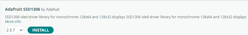
Click install. If it asks you to install dependencies go ahead and do so.
For reference, you can include it into a project by going to Sketch -> Include Library and click “Adafruit_SSD1306”. This does not need to be done in this sketch as it is already included.
The library reference where you can find all of the functions avaliable can be found here:
https://adafruit.github.io/Adafruit_SSD1306/html/class_adafruit___s_s_d1306.html
The first thing that we need to do is to define the length and width of our OLED in pixels.
byte screenWidth = 128;
byte screenHeight = 64;
Next, we have to define the I2C address of our OLED. I2C is a communication protocol that uses unique device addresses to communicate data. You do not need to understand anything about I2C other than the address for the OLED is 0x3C.
byte screenAddress = 0x3C;
What does 0x3C mean? Well, that number starts with “0x” because it is in hexadecimal. Hexadecimal is a base 16 numbering system that uses letters to represent numbers 10 – 15. These are letters A – F. Our day-to-day numbers are base 10 and are referred to as decimal numbers. 0x3C is 60 in decimal. You could write the address as 60 but I2C addresses are generally done in hex.
byte screenAddress = 0x3C;
Next, is the constructor for the class. The constructor contains a name, the screen’s width, the screen’s height, and a reference to the Wire object. That last one is a bit complicated, so we won’t worry about it. Just know that you need the “&Wire” as the last parameter. To break that down into a table:
| Parameters | Description |
|---|---|
| display | This is the name of the class we are creating. This is just like the “pixels” in the Neopixel projects. |
| screenWidth | This is the screen’s width in pixels (128) |
| screenHeight | This is the screen’s height in pixels (64) |
| &Wire | This is a reference to the Wire class. Don’t worry about understanding this right now. |
Adafruit_SSD1306 display(screenWidth, screenHeight, &Wire);
A few things need to be done in the setup() function. First, we have to initialize the OLED with the begin function. The “SSD1306_SWITCHCAPVCC” that is passed is just telling the OLED to create its own IO voltage. It’s basically creating a higher voltage than the MC Trainer can supply to support itself. We also have to pass the I2C address to it.
display.begin(SSD1306_SWITCHCAPVCC, screenAddress);
Next, the screen is cleared with the clearDisplay function.
display.clearDisplay();
Once loaded with data, the OLED needs to be told to display it with the display function. This works exactly the same as the show function with the Neopixels. In this case we’ve loaded the clear screen data.
display.display();
Now we set the cursor to coordinates (0,0). This (0,0) is different from a normal graph. The (0,0) for the OLED starts in the top left corner.
display.setCursor(0, 0);
Next, we will set the size of the text to be displayed.
display.setTextSize(1);
Lastly for setup we have to tell the OLED what color the text is with the setTextColor function. This OLED can only display white.
display.setTextColor(SSD1306_WHITE);
We are now ready to print some text! This works exactly the same as the Serial functions.
display.println("Hello World!");
Once the data is loaded, we have to display it with the display function.
display.display();
There is nothing in the loop() function in this project.
void loop() {
}
//////////////////////////////////////////////////////////////
Project 6.01 Changing Color with the Potentiometer
In this project, you'll harness the power of the potentiometer to change the color of the onboard NeoPixels using the HSV (Hue, Saturation, Value) color model!
This project will demonstrate the use of a potentiometer to control the color of the Neopixels. As the potentiometer rotates, the color of the Neopixels will change.
Project Code:
/////////////////////////////////////////////////////
// 6.01 - Changing Color with Potentiometer

#include <Adafruit_NeoPixel.h>

byte value = 255;
byte saturation = 255;

byte dataPin = 10;
byte numberOfPixels = 2;
byte brightness = 10;

byte potPin = A0;

Adafruit_NeoPixel pixels(numberOfPixels, dataPin, NEO_GRB + NEO_KHZ800);
void setup() {
  Serial.begin(9600);

  pinMode(potPin, INPUT);

  pixels.begin();
  pixels.setBrightness(brightness);
}

void loop() {

  int potValue = analogRead(potPin);
  long colorValue = map(potValue, 0, 1023, 0, 65535);

  pixels.setPixelColor(0, pixels.ColorHSV(colorValue, saturation, value));
  pixels.setPixelColor(1, pixels.ColorHSV(colorValue, saturation, value));
  pixels.show();

}
/////////////////////////////////////////////////////
*If you’re copying and pasting the code, or typing from scratch, delete everything out of a new Arduino sketch and paste / type in the above text.
After declaring variables, in the setup() function Serial is initialized, the pinMode of the potPin is set, the Neopixels are initialized and their brightness is set.
void setup() {
  Serial.begin(9600);

  pinMode(potPin, INPUT);

  pixels.begin();
  pixels.setBrightness(brightness);
}
In the loop() function, an int variable called potValue is created to hold the analog value read from the pot.
int potValue = analogRead(potPin);
At this point we have a problem. We have a potentiometer value somewhere between 0 and 1023 (10-bit) but our color range goes from 0 – 65535 (16-bit). This is where the map function comes in. The map function allows us to map two value ranges together linearly. This is much less scary than it sounds. Essentially, it will make 0 on the potentiometer equal 0 on the color range, and 1023 on the potentiometer equal 65535 on the color range. For example, if the potentiometer value read was 543 the map function would return a value of 34785.
We can check this by using the equation:
1.) (potValue * MaxHueValue) / MaxPotValue = MappedValue
2.) (543 * 65535)/1023 = 34,785
The map function takes five parameters. It takes the value to map, the min value of that range, the max value of that range, the min value of the range to be mapped to, and the max value of the range to be mapped to. See the table below:
| Parameters | Value |
|---|---|
| Value to map | analogValue read from pot |
| Min value of that range | 0 |
| Max value of that range | 1023 |
| Min value of the range to be mapped to | 0 |
| Max value of the range to be mapped to | 65535 |
long colorValue = map(potValue, 0, 1023, 0, 65535);
Lastly, the value that was mapped is written to the Neopixels and shown.
pixels.setPixelColor(0, pixels.ColorHSV(colorValue, saturation, value));
pixels.setPixelColor(1, pixels.ColorHSV(colorValue, saturation, value));
pixels.show();
Project 6.00 Using the Potentiometer
In this project, you'll learn how to read the values from a potentiometer and display them using the Serial Monitor!
This project introduces the potentiometer and shows how to use it. A potentiometer is a special type of resistor that allows us to change its resistance value. This feature makes potentiometers very useful for tasks like adjusting the volume on speakers or controlling the brightness of lights, where we need to vary resistance to control an electrical current.
Project Code:
///////////////////////////////////////////////////////////
// 6.00 - Using The Potentiometer

byte potPin = A0;

void setup() {
  Serial.begin(9600);
  pinMode(potPin, INPUT);
}

void loop() {
 int potValue = analogRead(potPin);

 Serial.print("The pot value is at: "); Serial.println(potValue);
 delay(100);
}
///////////////////////////////////////////////////////////
*If you’re copying and pasting the code, or typing from scratch, delete everything out of a new Arduino sketch and paste / type in the above text.
First, we declare the pin that the potentiometer is connected to as potPin. This variable declaration is different from those you’ve seen so far because it starts with an “A”. This “A” means that the pin we are connecting to is an analog pin. Analog pin refers to a pin that can read analog values. A digital value would be a 1 or a 0 (5v or 0v), but an analog value can be anything in between. Not all pins can be used as analog pins on the MC Trainer.
byte potPin = A0;
In the setup you’ll notice that the pin is still an INPUT pin. This is because we are using the pin to read a value. It does not matter if it is digital or analog, it is still an input.
pinMode(potPin, INPUT);
You can read the analog voltage at an analog pin by using the analogRead function. analogRead returns a 10-bit value (0 – 1023) that represents the voltage at that pin. 5v would be 1023, ~2.5v would be 512, and 0v would be 0.
int potValue = analogRead(potPin);
After that we print the value read out into the Serial port and delay 100 milliseconds. Make sure and open the Serial port to see the data being printed.
Serial.print("The pot value is at: "); Serial.println(potValue);
delay(100);
Try rotating the knob of the potentiometer to see the range of values produced!
Project 5.05 Individually Fading Neopixels
In this project we will create a dynamic light display using two Neopixels. The objective is to smoothly transition one Neopixel from off to full brightness while simultaneously dimming the other from full brightness to off, and then reversing this process.
In this project we will create a dynamic light display using two Neopixels. The objective is to smoothly transition one Neopixel from off to full brightness while simultaneously dimming the other from full brightness to off, and then reversing this process.
////////////////////////////////////////////////////////
#include <Adafruit_NeoPixel.h>

byte dataPin = 10;
byte numberOfPixels = 2;
byte brightness = 255;

Adafruit_NeoPixel pixels(numberOfPixels, dataPin, NEO_GRB + NEO_KHZ800);
void setup() {
  pixels.begin();
  pixels.setBrightness(brightness);
  pixels.show();
}

void loop() {

  for (uint8_t i = 0; i < 255; i++) {
    pixels.setPixelColor(0, pixels.Color(i, 0, 0));
    pixels.setPixelColor(1, pixels.Color(255 - i, 0, 0));
    pixels.show();
    delay(5);
  }

  for (uint8_t i = 255; i > 0; i--) {
    pixels.setPixelColor(0, pixels.Color(i, 0, 0));
    pixels.setPixelColor(1, pixels.Color(255 - i, 0, 0));
    pixels.show();
    delay(5);
  }
}
////////////////////////////////////////////////////////
*If you’re copying and pasting the code, or typing from scratch, delete everything out of a new Arduino sketch and paste / type in the above text.
The setup of the Neopixels is the same as the other Neopixel projects, so we’ll skip straight to the loop() section. In the loop() there are two for-loops that control the behavior of the Neopixels:
void loop() {

  for (uint8_t i = 0; i < 255; i++) {
    pixels.setPixelColor(0, pixels.Color(i, 0, 0));
    pixels.setPixelColor(1, pixels.Color(255 - i, 0, 0));
    pixels.show();
    delay(5);
  }

  for (uint8_t i = 255; i > 0; i--) {
    pixels.setPixelColor(0, pixels.Color(i, 0, 0));
    pixels.setPixelColor(1, pixels.Color(255 - i, 0, 0));
    pixels.show();
    delay(5);
  }
}
The first for-loop counts from 0 to 255 and writes that value to Neopixel number 0. Since we are setting the green and blue values of that Neopixel to 0 and just writing to the red portion, this has the effect of increasing the brightness of that Neopixel with the count:
  for (uint8_t i = 0; i < 255; i++) {
    pixels.setPixelColor(0, pixels.Color(i, 0, 0));
The next line of code in the for-loop writes to Neopixel number 1. This time instead of writing the for-loop count directly to the Neopixel, we first subtract it from 255. If you remember from lesson 5.00, the Color function takes 8-bit values (0-255) to represent red, green, and blue. So if we subtract the current for-loop() count from 255 before we write it to the NeoPixel it gives us the inverse of the loop count. This effectively gives us an inverse brightness for Neopixel number 1 from Neopixel number 0.
pixels.setPixelColor(1, pixels.Color(255 - i, 0, 0));
Next, the neopixels are updated with the show() function and the program is delayed by 5 milliseconds. The program needs to be slowed down so we can actually see the Neopixel transition smoothly.
    pixels.show();
    delay(5);
  }
The Second for loop is the same as the first for-loop with the exception that the count is started from 255 and counts down to 0. This allows Neopixel number 0 to start at 255 and count down. The same inverse relationship is kept with Neopixel number 0 and Neopixel number 1.
  for (uint8_t i = 255; i > 0; i--) {
    pixels.setPixelColor(0, pixels.Color(i, 0, 0));
    pixels.setPixelColor(1, pixels.Color(255 - i, 0, 0));
    pixels.show();
    delay(5);
  }
This relationship can be elegantly illustrated with a graph of two cosine waves stacked on top of each other with one 180 degrees out of phase:

When one Neopixel is at it’s peak in terms of color intensity, the other is at it’s lowest point.
Project 5.04 Fading Neopixels Using Buttons
In this project, you'll learn how to gradually adjust the brightness of the onboard NeoPixels using buttons!
This project is a bit more complicated than the last. In this project the goal is to slowly fade a Neopixel on while a button is pressed but instead of the Neopixel shutting off when the button is released, it slowly fades off. Again, SW1 will control the left Neopixel, and SW2 will control the right Neopixel.
Project Code:
////////////////////////////////////////////////////////
// 5.04 - Fading Neopixels Using Buttons

#include <Adafruit_NeoPixel.h>

byte dataPin = 10;
byte numberOfPixels = 2;
byte SW1 = 1;
byte SW2 = 0;

bool pressed = LOW;

byte saturation = 255;
long neoPixelOneColor = 0;
long neoPixelTwoColor = 45000;
byte neoPixelOneBrightness = 0;
byte neoPixelTwoBrightness = 0;

Adafruit_NeoPixel pixels(numberOfPixels, dataPin, NEO_GRB + NEO_KHZ800);
void setup() {

  pixels.begin();

  pinMode(SW1, INPUT);
  pinMode(SW2, INPUT);
}

void loop() {
  if (digitalRead(SW1) == pressed) {
    if (neoPixelOneBrightness < 255) {
      neoPixelOneBrightness = neoPixelOneBrightness + 1;

    }
  }
  else {
    if (neoPixelOneBrightness > 0) {
      neoPixelOneBrightness = neoPixelOneBrightness - 1;
    }
  }

  if (digitalRead(SW2) == pressed) {
    if (neoPixelTwoBrightness < 255) {
      neoPixelTwoBrightness = neoPixelTwoBrightness + 1;
    }
  }
  else {
    if (neoPixelTwoBrightness > 0) {
      neoPixelTwoBrightness = neoPixelTwoBrightness - 1;
    }
  }

  pixels.setPixelColor(0, pixels.ColorHSV(neoPixelOneColor, saturation, neoPixelOneBrightness));
  pixels.setPixelColor(1, pixels.ColorHSV(neoPixelTwoColor, saturation, neoPixelTwoBrightness));

  pixels.show();

  delay(10);
}
////////////////////////////////////////////////////////
*If you’re copying and pasting the code, or typing from scratch, delete everything out of a new Arduino sketch and paste / type in the above text.
This sketch introduces two new byte type variables from the last. These two variables are used to keep track of the individual brightness of each Neopixel:
byte neoPixelOneBrightness = 0;
byte neoPixelTwoBrightness = 0;
Moving on to the loop(), we once again need to make a decision. Is the button pressed? For this we will use an if-statement:
if (digitalRead(SW1) == pressed) {
We can make increasingly complex decisions with an if-statement inside another if-statement. In this example we set the color using ColorHSV. This makes it very easy for us to set the brightness of an individual pixel. Remember that the last parameter for ColorHSV is the “Value” of the Neopixel (brightness). It is important to note that this function takes 8-bit number for value, so it’s numbers between 0-255. If we pass a value over 255 unexpected things can happen. For that reason, we have to check and see if the brightness value for this pixel is less than 255 before we increase the brightness any.
if (neoPixelOneBrightness < 255) {
If the button is pressed, we need to increase the brightness of the Neopixel associated with that button (if it is below 255). In this example we increase the brightness variable by one every time that the loop() runs and the button is found to be pressed.
neoPixelOneBrightness = neoPixelOneBrightness + 1;
If the associated button is not pressed, the else part of the if-statement executes. Along with not being able to pass numbers above 255 for the value parameter of ColorHSV we cannot pass numbers below 0 for the value parameter. It doesn’t make sense to have a brightness below 0. For that reason, we have to check and see that the associated brightness variable is greater than 0 before subtracting 1:
if (neoPixelOneBrightness > 0) {
If it is above 0 we can subtract 1 from it:
neoPixelOneBrightness = neoPixelOneBrightness - 1;
The exact same thing happens with the other button and Neopixel:
if (digitalRead(SW2) == pressed) {
  if (neoPixelTwoBrightness < 255) {
    neoPixelTwoBrightness = neoPixelTwoBrightness + 1;
  }
}
else {
  if (neoPixelTwoBrightness > 0) {
    neoPixelTwoBrightness = neoPixelTwoBrightness - 1;
  }
}
Next, we need to update the Neopixels with their associated brightness values. Remember that the first Neopixel is number 0 and the second Neopixel is number 1. All we have to do is address the Neopixels and pass the new brightness values to ColorHSV.
pixels.setPixelColor(0, pixels.ColorHSV(neoPixelOneColor, saturation, neoPixelOneBrightness));

pixels.setPixelColor(1, pixels.ColorHSV(neoPixelTwoColor, saturation, neoPixelTwoBrightness));
After we update the Neopixels we have to show the new brightness:
pixels.show();
Lastly, there is a delay added so that we can see the incremental changes. Try deleting this delay and see what happens!
  delay(10);
}
////////////////////////////////////////////////////////
Let’s do a brief recap.
First, we checked to see if a button was pressed. If the button was pressed, we checked to see if the brightness associated with the Neopixel was below 255. If it was, we increased its brightness by 1.
If the button was not pressed, we checked to see if the brightness of the associated Neopixel was greater than 0. If it was, we decreased its brightness by 1.
Next, we updated the Neopixels with the correct brightness variables. Then showed the Neopixel updates and added a small delay.
Project 5.03 Individually addressing Neopixels using buttons
In this project, you'll learn how to control the color of each onboard NeoPixel individually using buttons!
The goal of this project is to control the left Neopixel with SW1 and the right Neopixel with SW2. The left Neopixel will turn on when SW1 Is pressed, and the right Neopixel will turn on when SW2 is pressed. They will turn off when their respective buttons are not pressed.
Project Code:
////////////////////////////////////////////////////////
// 5.03 – Individually addressing Neopixels using buttons

#include <Adafruit_NeoPixel.h>

byte dataPin = 10;
byte numberOfPixels = 2;

byte SW1 = 1;
byte SW2 = 0;

bool pressed = LOW;

byte saturation = 255;
long neoPixelOneColor = 0;
long neoPixelTwoColor = 45000;

Adafruit_NeoPixel pixels(numberOfPixels, dataPin, NEO_GRB + NEO_KHZ800);
void setup() {
  pixels.begin();

  pinMode(SW1, INPUT);
  pinMode(SW2, INPUT);
}

void loop() {
  if (digitalRead(SW1) == pressed) {
    pixels.setPixelColor(0, pixels.ColorHSV(neoPixelOneColor, saturation, 255));
  }
  else {
    pixels.setPixelColor(0, pixels.ColorHSV(neoPixelOneColor, saturation, 0));
  }

  if (digitalRead(SW2) == pressed) {
    pixels.setPixelColor(1, pixels.ColorHSV(neoPixelTwoColor, saturation, 255));

  }
  else {
    pixels.setPixelColor(1, pixels.ColorHSV(neoPixelTwoColor, saturation, 0));
  }

  pixels.show(); // Show the Neopixel's color
}
////////////////////////////////////////////////////////
*If you’re copying and pasting the code, or typing from scratch, delete everything out of a new Arduino sketch and paste / type in the above text.
Like previous sketches, we want to make a decision based on if the buttons are pressed or not. In order to do so, we need to use if-statements.
if (digitalRead(SW1) == pressed) {
Next, we need to add the code that turns on the Left Neopixel if SW1 is pressed.
pixels.setPixelColor(0, pixels.ColorHSV(neoPixelOneColor, saturation, 255));
Let’s break this function down again. In the setPixelColor function there are two parameters. The first is the address of the Neopixel you’d like to target.
Neopixels are all chained together in one big line. Like most things in programming the line count starts at 0. The Neopixel on the left is first in line so it’s Neopixel number 0. The Neopixel on the right is the second in line so it’s Neopixel number 1.
So, in this case since we have passed a 0 as our first parameter in the setPixelColor function, we are addressing the Neopixel on the left.
pixels.setPixelColor(0
The second parameter of setPixelColor is the pixel’s color. In this case we use the ColorHSV function to set that.
The third parameter of the ColorHSV function is the most important here. Remember, It’s the value of the color (brightness). If we set this to 255, the color is full brightness and if we set it to 0, the Neopixel is off. So, when SW1 is pressed we want to set the Neopixel to full brightness:
    pixels.setPixelColor(0, pixels.ColorHSV(neoPixelOneColor, saturation, 255));
}
And when the SW1 is not pressed we want to turn the Neopixel off:
else {
  pixels.setPixelColor(0, pixels.ColorHSV(neoPixelOneColor, saturation, 0));
}
The same process is repeated for the Neopixel on the right, but you’ll notice that Neopixel number 1 is addressed instead:
if (digitalRead(SW2) == pressed) {
  pixels.setPixelColor(1, pixels.ColorHSV(neoPixelTwoColor, saturation, 255));
}
else {
  pixels.setPixelColor(1, pixels.ColorHSV(neoPixelTwoColor, saturation, 0));
}
Then to display these colors all we need to do is call the show() function:
  pixels.show(); // Show the Neopixel's color
}
////////////////////////////////////////////////////////
And the loop repeats.
To change the color that is being displayed, change the neoPixelOneColor and neoPixelTwoColor variables. This website will give you the HSV and RGB color codes for a desired color:
https://www.rapidtables.com/web/color/color-picker.html
Project 5.02 Using ColorHSV
In this project, you'll learn how to gracefully transition between a spectrum of colors using the onboard NeoPixels with the HSV (Hue, Saturation, Value) color model!
There are multiple ways to set the color of the Neopixels. Until now we have used the Color function to set the RGB color of the Neopixel. We can also use the function ColorHSV to set the color a different way. HSV stands for Hue, Saturation, and Value. Hue refers to the color of the Neopixel, Saturation refers to how white the Neopixel is, and Value refers to how bright the Neopixel is. Hue in this case is a 16-bit value (0 - 65535), while Saturation and Value are 8-bit values (0 - 255). Which color method you use is totally up to you and mostly comes down to preference and application.
Note: Using ColorHSV does make it easier to loop through the entire color spectrum.
Project Code:
////////////////////////////////////////////////////////
// 5.02 - Using ColorHSV

#include <Adafruit_NeoPixel.h>
byte saturation = 255;
byte value = 255;

byte dataPin = 10;
byte numberOfLEDs = 2;
byte brightness = 10;

Adafruit_NeoPixel pixels(numberOfLEDs, dataPin, NEO_GRB + NEO_KHZ800);
void setup() {
  Serial.begin(9600);
  pixels.begin();
  pixels.setBrightness(brightness);
}

void loop() {
  for (long hue = 0; hue < 65536; hue++) {
    pixels.setPixelColor(0, pixels.ColorHSV(hue, saturation, value));
    pixels.setPixelColor(1, pixels.ColorHSV(hue, saturation, value));
    pixels.show();
    delayMicroseconds(3);
  }

}
////////////////////////////////////////////////////////
*If you’re copying and pasting the code, or typing from scratch, delete everything out of a new Arduino sketch and paste / type in the above text.
Two variables are used to set the saturation and value parameters. These values are not changed throughout the course of the program. Feel free to change these values and see how it effects the program!
byte saturation = 255;
byte value = 255;
In the loop section of the program, all possible hue values are looped through and displayed. Remember, hue is represented by a 16-bit value (0 - 65535).
void loop() {
  for (long hue = 0; hue < 65536; hue++) {
    pixels.setPixelColor(0, pixels.ColorHSV(hue, saturation, value));
    pixels.setPixelColor(1, pixels.ColorHSV(hue, saturation, value));
Every time the hue value is changed, the Neopixels are updated to provide a smooth transition between colors.
pixels.show();
A small delay is incorporated to slow down the color cycling. This delay function uses microseconds to delay instead of milliseconds. 1 second is 1000 milliseconds and 1 millisecond is 1000 microseconds. That means that we are delaying 3 millionths of a second here! We use microseconds becuase we want the color to transition smoothly. There are 65,536 colors being displayed in the for-loop. Using the regular delay function between each one would make it look choppy and make the full color cycle take too long. Change the delayMicroseconds to delay and see what happens!
    delayMicroseconds(3);
  }
}
////////////////////////////////////////////////////////